Introduction
NET-G3A Operator’s Manual
1-10
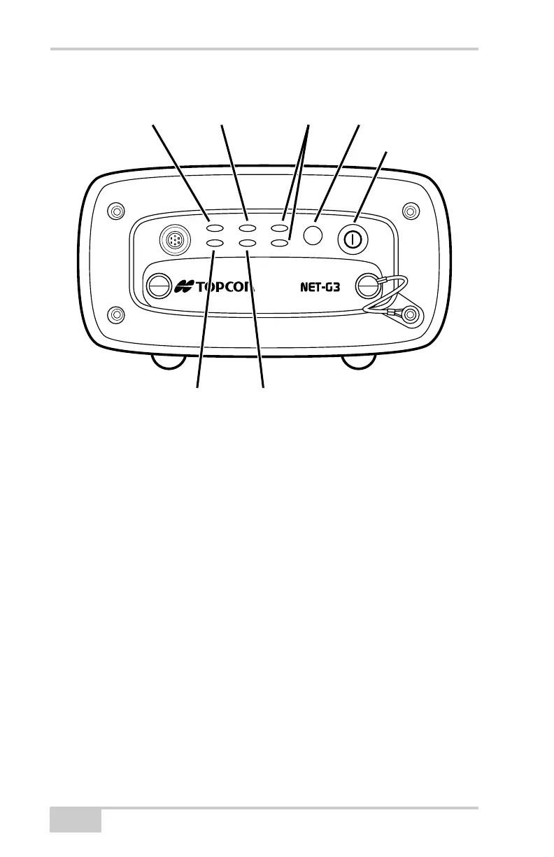
Figure 1-2. Net-G3A MINTER
The PWR LEDs display the status of power supplied from the
corresponding external or internal power source.
• Solid Green – The receiver accepts power from an external power
source connected to the corresponding PWR port. This power is
within an allowed operating voltage range (6–28 V DC).
The corresponding backup battery is fully charged.
• Solid Yellow – The receiver accepts power from an external
power source connected to the corresponding PWR port, and this
power is within an allowed operating voltage range (6–28 V DC),
but is not being used to power the receiver.
• Solid Red – A power failure has occurred (with the connected
power source) or power is not supplied to the corresponding PWR
port. For details, see “Powering Problems” on page 5-2.
• Green blinks plus red blinks – The receiver accepts power from
an external power source connected to the corresponding PWR
port and is charging the corresponding battery.
FN
STAT LINK PWR 1
REC RX/TX PWR 2
A
STAT LED LINK LED Power LEDs Function Button
Power Button
REC LED RX/TX LED
Net-G3A_OM_Book.book Page 10 Thursday, May 14, 2009 8:49 AM