Do you have a question about the Topcon MR-2 and is the answer not in the manual?
Outlines the terms and conditions for using Topcon products and associated software.
Provides essential safety guidelines and warnings for operating the receiver.
Explains the typographical and formatting conventions used throughout the manual.
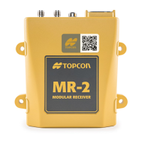
Details the key features and capabilities of the MR-2 GNSS receiver.
Instructions for verifying the contents and condition of the receiver upon unpacking.
Information on how to obtain technical assistance and support for the receiver.
Guidance on accessing product information and support resources via the Topcon website.
Describes the communication and power connectors on the MR-2 receiver.
Details the primary and secondary antenna connectors for signal reception.
Explains the function and use of the OAF for enabling receiver features.
Information on the HD2 system for heading and inclination determination.
Lists standard cables and accessories included with or available for the MR-2 receiver.
Provides guidance and dimensions for securely mounting the MR-2 receiver.
Guides the user through connecting cables and antennas to the MR-2.
Step-by-step instructions for setting up serial cable connections.
Step-by-step instructions for setting up Ethernet cable connections.
Instructions for downloading and installing the TRU software for receiver configuration.
Procedures for powering the MR-2 receiver on and initiating shutdown.
Explains how the receiver is powered using an external source.
Details on connecting the receiver to a 9-36 VDC power supply.
Information on the effects and duration of power cycling the receiver.
Steps to establish a connection between the MR-2 receiver and TRU software.
Guides on customizing and connecting via Ethernet settings.
Details on configuring the receiver's Ethernet network settings.
How to check the IP addresses assigned to the receiver's main and auxiliary boards.
Procedure to configure a static IP address on a laptop for connection.
Instructions to view the current password for receiver access.
Steps to change the default or current password for the receiver.
Procedure to reset the receiver to its default settings or factory state.
Steps for establishing a TRU connection using the receiver's Ethernet interface.
Guides for configuring the MR-2 to operate as a base station.
Instructions for setting up the GNSS antenna type for the receiver.
Procedure for configuring the input/output modes of the receiver's serial ports.
Instructions for configuring the TCP port settings for receiver communication.
Optional configuration for adding specific messages to serial port output.
Optional procedure for modifying existing messages in serial port output.
Guides for configuring the MR-2 to operate as a rover.
Procedure to define the positioning mode for the receiver's operation.
Describes the purpose and location of the receiver's status LEDs.
Explains the status and OAF type indicated by the Power LED.
Details the status of the Ethernet connection indicated by the Ethernet LED.
Describes how STAT LEDs indicate satellite tracking status and signal quality.
Highlights the MR-2's use as a GNSS sensor in surveying and construction.
Describes configuring the MR-2 as a base receiver for RTK corrections.
Explains the MR-2's role in deriving heading and inclination using dual antennas.
Basic steps to verify connections and settings before seeking technical help.
Solutions for issues related to the receiver's power supply and connections.
Addresses issues where the receiver cannot establish a connection to a computer.
Procedure for clearing the receiver's NVRAM to reset settings.
Guidelines for proper cleaning and storage of the MR-2 receiver.
Provides overarching safety warnings for the use of TPS receivers.
Details warnings related to tampering and proper handling of the receiver.
Advisories on proper usage to ensure measurement accuracy and product longevity.
Provides general specifications including enclosure, dimensions, and weight.
Details the pin-out specifications for various connectors on the MR-2.
Specific pin configuration for the main Deutsch DTM 12-pin connector.
Specific pin configuration for the Ethernet receptacle.
Pinout details for the receiver end of the cable harness.
Pin configuration for the power connector part of the cable harness.
Pinout details for the COM1 serial connector of the cable harness.
Pinout details for the COM2 serial connector of the cable harness.
Pinout specifications for the optional power adapter cable connector.
Pinout specifications for the receiver side of the Ethernet cable.
Information regarding the MR-2's compliance with FCC Class A digital device limits.
Details on the MR-2's compliance with Canadian ICES-003 and RSS standards.
Information on compliance with European R&TTE and EMC directives.