Cable and Antenna Connections
13
P/N: 1011907-01
System Setup
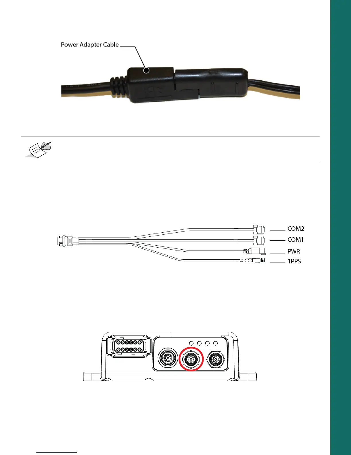
4. Connect the other end (SAE connector) of the power adapter cable to a 9-36 VDC power supply unit with
an SAE connector, as shown in
Figure 7.
Figure 7: Power Adapter Cable to Power Supply Unit
5. Verify the power supply is on and supplying power.
6. Make sure the MR-2 LED is lit solid, which indicates it is receiving power.
Step 2: Connect to a Computer or Display Unit and RTK Correction Source
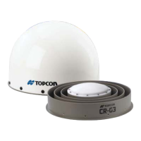
1. Connect the COM1 serial port connector on the cable harness to the serial port on the computer or display.
2. (Optional) If the MR-2 is RTK enabled, connect the COM2 serial port connector to the serial port of the RTK
correction source.
Figure 8: Cable Harness – COM1 and COM2 Serial Ports
Step 3: Connect a Single Antenna
To connect a single external antenna for precise positioning:
1. Mount the GNSS antenna on a rigid surface.
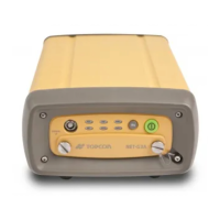
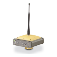
2. Connect the antenna cable to the primary antenna connector circled in red in Figure 9.
Figure 9: Primary Antenna Connector
3. Make sure the antenna cable is connected to the antenna.
You can also create a custom cable to connect a 9-36 VDC directly to the 3-pin Deutsch connector on
the break-out harness.