Connector Specifications
60
P/N: 1011907-01
Specifications
Connector Specifications
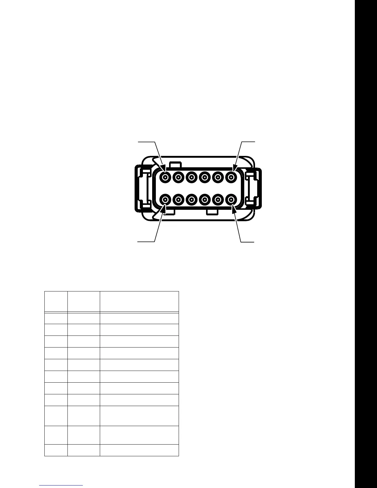
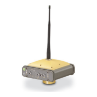
The MR-2 has two antenna connectors, and one port connector for power and data upload/download.
Main Connector
The power connector (Figure 65) is a sealed receptacle, Deutsch DTM Series 12-pin connector located on the
front of the receiver.
Figure 65: Power Connector
Table 7 provides the power connector specifications.
a. These specifications wills vary depending on the number of satellites used, obstructions, satellite geometry (PDOP),
occupation time, multipath effects, and atmospheric conditions. Performance may be degraded in conditions with high
ionospheric activity, extreme multipath, or under dense foliage. For maximum system accuracy, always follow best
practices for GNSS data collections.
Table 7. Main Connector Specifications
No.
Signal
Name
Direction
1 GND_IN Ground Input
2 PWR_IN Power Input
3 TXD1 Output
4 RXD1 Input
5 RXD2 Input
6 TXD2 Output
7 GND Ground
8 IGN Input
9
CAN_H1/
a
RXD3
Input/Output
10 CAN_L1/
TXD3
Input/Output
11 PPS Pulse Per Second Output