LED Indicators
10
P/N: 1011907-01
LED Indicators
The LED indicators able you to control receiver power and data recording. The LEDs display the status of the
power, Ethernet connectivity, and satellite tracking. This chapter describes the different LED blink patterns and
what they mean.
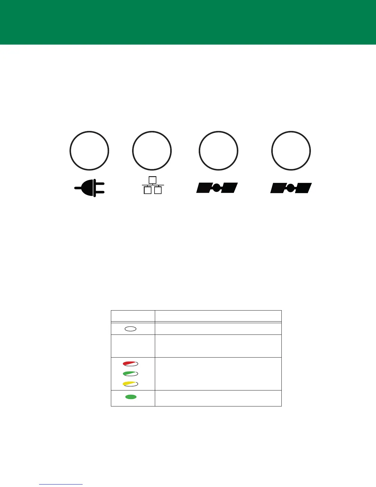
Figure 4: LED Indicators
Receiver Status LEDs
There are four status LEDs to provide you information about power Ethernet connectivity, and tracked satellites.
This section describes the color and behavior of each LED.
Power LED
The Power LED indicates whether the receiver is on or off, and to indicate the status and type of OAF loaded.
Power Ethernet
STAT
(Primary Antenna)
STAT
(Secondary Antenna)
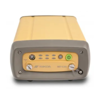
Table 3. Power LED Patterns
LED Color Description
When the LED is off, the receiver is off.
When the LED is blinking or solid, the receiver is
on and an OAF is loaded. See below for the types
of OAF.
When the LED continuously blinks between red,
green and yellow, a standalone positioning OAF is
loaded.
When the LED is solid green, an RTK-enabled OAF
is loaded.