MINTER Description and Configuration
P/N 7010-0935
3-9
MINTER Description and
Configuration
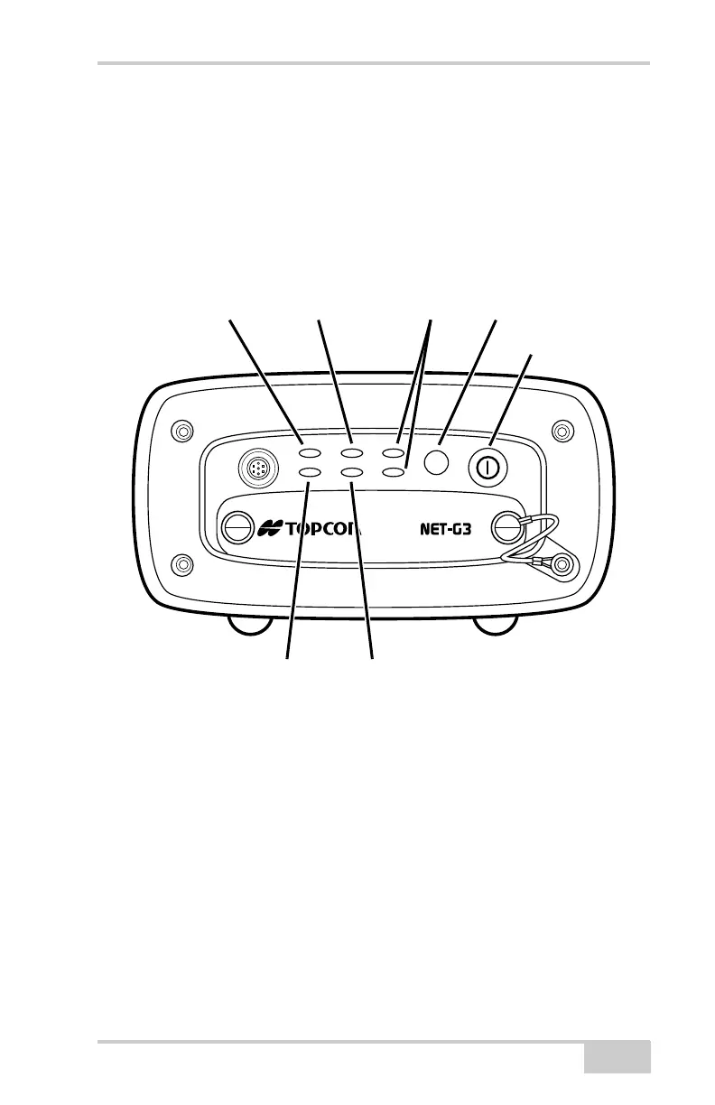
The Minimum INTERface (MINTER) consists of two keys (power
and FN) that control the receiver’s operation, four LEDs that display
the receiver’s operational status, and two LEDs that display the power
status (Figure 3-8).
Figure 3-8. MINTER
The MINTER performs the following functions. For more
information about using the MINTER, see “MINTER Operation” on
page 3-16.
• Turns the receiver on or off; puts it in Sleep mode.
• Turns data recording on or off (FN button).
• Changes the receiver’s information mode.
• Shows the number of GPS (green) and GLONASS (orange)
satellites being tracked (STAT LED).
• Shows the data recording status (REC LED).
• Shows each time data is recorded to the memory (REC LED).
FN
STAT LINK PWR 1
REC RX/TX PWR 2
A
STAT LED LINK LED Power LEDs Function Button
Power Button
REC LED RX/TX LED
Net-G3A_OM_Book.book Page 9 Thursday, May 14, 2009 8:49 AM