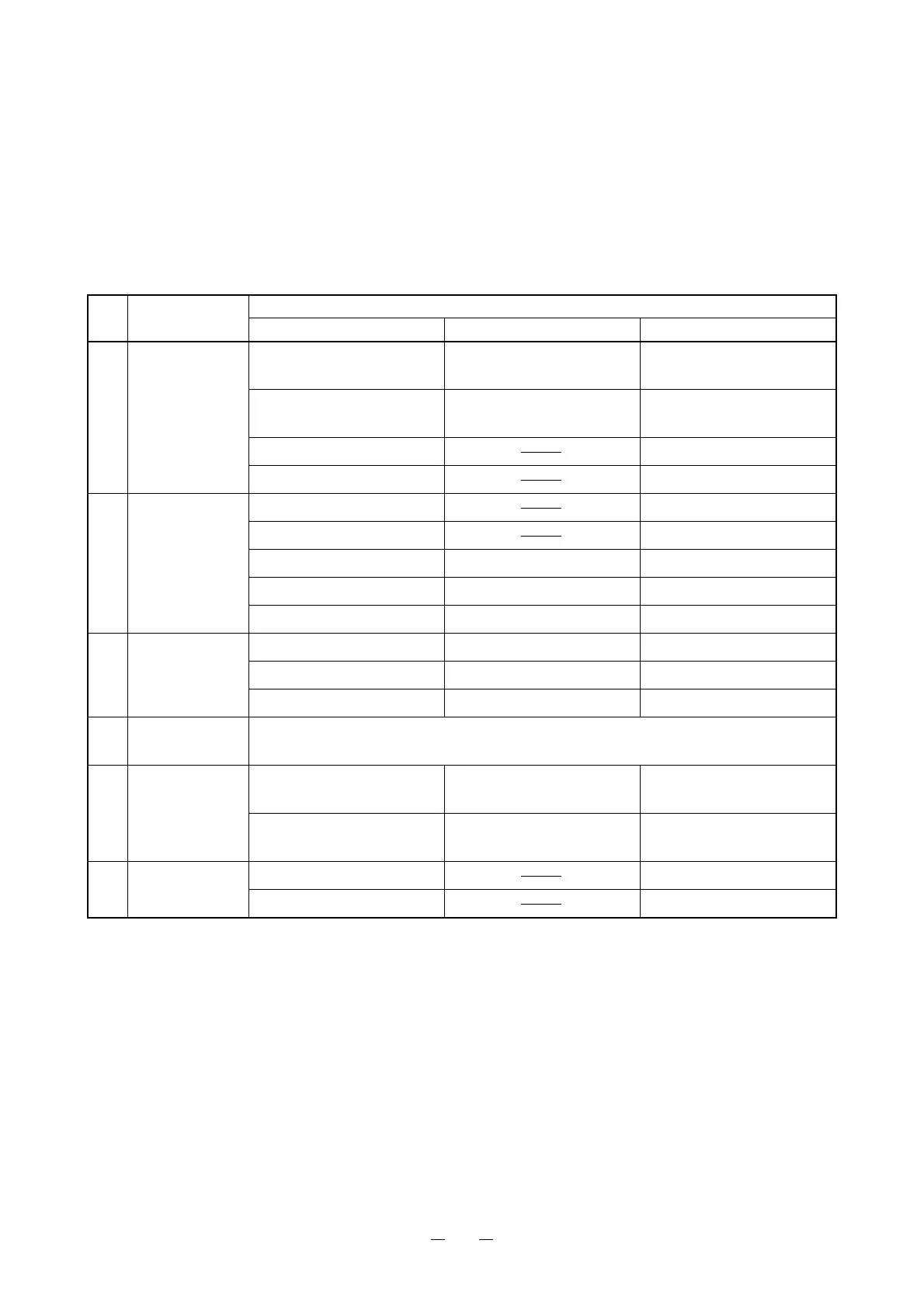
31
2-3-5 Wiring check
This section describes the special checks that are required when the problem is diagnosed as “Wiring check”
in the frowcharts of “2-3-4 Trouble shooting”. The number in parentheses for the wiring check in “2-3-4 Trou-
ble shooting” corresponds to “No.” in the following table.
Use the tester to check between “From” and “To” in “Area for checking”.
If the wire passes through a part on the way, such a part is shown in “Via”.
Check it at the same time. Refer to “Electric parts arrangement”.
No. Remarks
Area for checking
From Via To
(1) Disconnection Inlet (L) Fuse holder (F1)
~ Power switch (SW1)
SW power supply (P1-3)
Inlet (N) Fuse holder (F2)
~ Power switch (SW1)
SW power supply (P1-1)
Connector (P52-1) Pilot lamp (P.L)
Connector (P52-2) Pilot lamp (P.L)
(2) Disconnection/
Short circuit
Connector (P2-1) Halogen lamp (H.L)
Connector (P2-2) Halogen lamp (H.L)
Connector (J1-3) Connector (P2-3~P1-1) Volume (CN1-1)
Connector (J1-4) Connector (P2-4~P1-2) Volume (CN1-2)
Connector (J1-5) Connector (P2-5~P1-3) Volume (CN1-3)
(3) Disconnection/
Short circuit
Connector (J1-3) Connector (P2-3~P1-1) Volume (CN1-1)
Connector (J1-4) Connector (P2-4~P1-2) Volume (CN1-2)
Connector (J1-5) Connector (P2-5~P1-3) Volume (CN1-3)
(4) Disconnection/
Short circuit
Same as Wiring check (2).
(5) Disconnection Connector (P2-1) Diode (D2) External fixation LED
(LED2-A)
Connector (P2-3) Resistor (R1) External fixation LED
(LED2-K)
(6) Disconnection Connector (CN2-4) Switch (SW2-4)
Connector (CN2-8) Switch (SW2-3)