10
desired open position when the open limit switch approaches it.
The magnet component with S pole must be installed at left side and the magnet component with N
pole must be installed at right side from the view inside of property.
Ensure magnet center to align with the marked line above !
The magnets should be 25~30mm (1-1.2”) away from the Limit Switch Box. If it is too near or too far, the
switches will fail to work. Adjust the position of the magnets until the positions of the opening and closing
meet the requirement.
Connection of the Power Supply
WARNING: NEVER connect the gate opener to the power outlet before all the installations have
been done.
NOTE:
1. If batteries as are chosen as the power source, Marine or Automotive Type Battery is required. The
batteries should be waterproof type, or be placed in water proof circumstance.
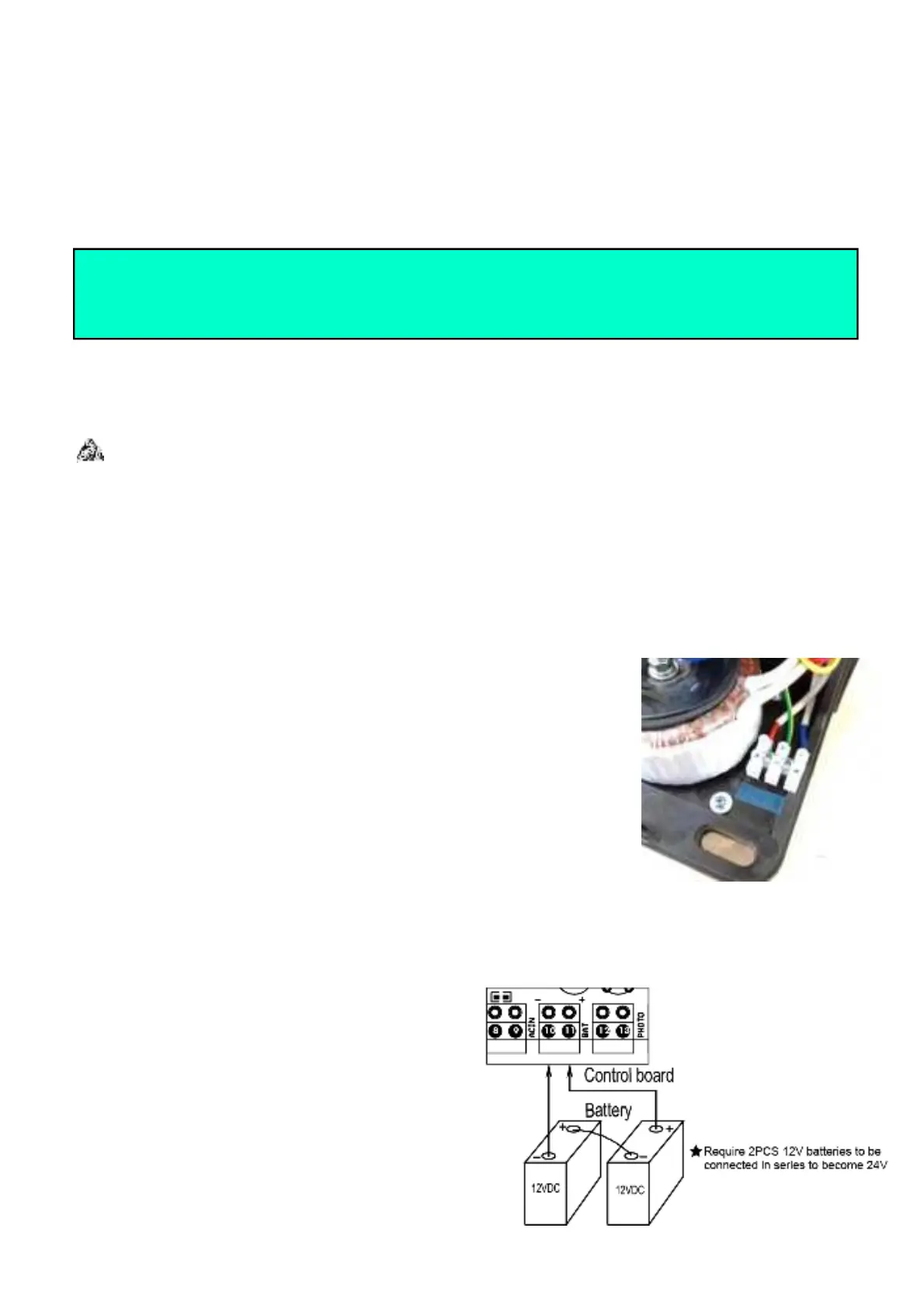
2. 2 PCS 12VDC batteries can be connected in series to function as 24VDC. The following diagram
shows on how to connect 2 PCS batteries in series.
3. Please note that the wire connection of the power supply system is very important. Incorrect wire
connection will damage the control board.
Power Mode 1. Only use the AC electricity as the
power source
The power supply cord should be at least 3×0.75mm
2
(3C×18AWG). Connect
the live wire, neutral wire and earth wire to the “L”, “N” and “PE” terminals
respectively.
NOTE: The power supply cord is not included in the package.
Power Mode 2. By AC electricity and back-up batteries, only use the AC
electricity to charge the batteries
If the AC electricity failure happens rarely (less than 8
hours per day), then you can use minimum 5Ah
2*12VDC batteries as back-up power source in case of
AC power failure. In this situation, you can connect the
AC electricity following the “Power Mode 1” and the
batteries to the BAT terminal of the control board
directly as the below wiring diagram.
Warning: Improper magnets installation may cause the gate crash into end barrier,
which is very dangerous !