Fig.
1
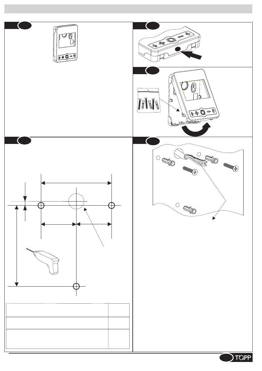
Installazione selettore - Switch installation - Installation sélecteur - Instalación selector - Installation des Schalters
Fig.
2
IT- Muro (fissaggio con tassello) SP-Pared (fijación con taco)
EN-Wall (fastening with anchor bolts) DE-Mauer (Befestigung mit Dübeln)
FR- Mur (fixation avec tasseau)
F
Ø4
Ø2.25÷Ø2.5
IT- Superficie di fissaggio SP-Superficie de fijación
EN-Fastening surface DE-Befestigungsfläche
FR-Surfaces de montage
IT- Alluminio (utilizzare solo vite)
FR-Aluminium (utiliser seulement des vis)
EN-Aluminum (use only screws)
SP-Aluminio (utilizar sólo tornillo)
DE- Aluminium (nur Schrauben verwenden)
Fig.
4
F
Fig.
4
24,5 mm
45,8 mm
= =
F
F
1÷2
IT-Nel caso di fissaggio a muro, inserire completamente i tasselli nei fori
realizzati. Avvitare le 2 viti AF superiori fino a circa 10mm dalla battuta
(Vedi Fig.6).
N.B.La vite AF inferiore andrà fissata in seguito.
Nel caso di fissaggio su alluminio, stessa procedura senza tasselli.
Note: the lower AF screw will be fastened later.
If fastening to aluminum, proceed without the anchor bolts.
EN-When fastening to the wall, insert the bolts all the way into the
holes drilled. Fasten the 2 upper AF screws to about 10mm from the
surface. (See Fig.6)
N.B. La vis AF inférieure devra être fixée par après.
FR-Dans le cas d'un montage mural, insérer entièrement les chevilles
dans les trous percés. Serrer les 2 vis AF supérieures jusqu'à environ 10
mm de la butée (Voir Fig.6)
Dans le cas d'une fixation sur l'aluminium , même procédure, sans
tasseaux.
SP-En el caso de fijación a la pared , introducir completamente los
tacos en los agujeros realizados. Atornillar los 2 tornillos AF superiores
h as t a a p r o x i ma d a m e n t e 1 0 m m d e l t o p . ( Vé a s e F i g . 6 )
N.B.El tornillo AF inferior se fijará a continuación.
En el caso de fijación sobre aluminio,el mismo procedimiento sin tacos.
EN-Open the switch by pressing gently on the surface as shown in
fig.2. Turn the cover as shown in figure 3.
IT- Aprire il selettore applicando una leggera pressione sulla
superficie indicata in fig.2. Ruotare il coperchio come in figura 3.
DE-Den Schalter durch einen leichten Druck auf die in Abb.2 gezeigte
Fläche öffnen. Die Abdeckung gemäß Abbildung 3 drehen.
SP-Abrir el selector aplicando una ligera presión sobre la superficie
indicada en la fig.2. Girar la tapa tal como se muestra en la fig.3.
FR-Ouvrir le sélecteur en appliquant une légère pression sur la
surface indiquée dans la figure 2. Faire tourner le couvercle comme
dans la figure 3.
IT- Realizzare num.3 fori per fissaggio selettore
FR-Faire 3 trous pour la fixation du sélecteur
SP-Realizar 3 agujeros para fijar el selector
EN-Drill 3 holes for fastening of the switch
DE-3 Löcher für die Befestigung des Schalters
bohren
IT- Zona di pressione
EN-Pressure zone
FR-Zone de pression
SP-Zona de presión
DE-Druckbereich
IT- Ruotare
FR-Tourner
DE-Drehen
EN-Turning
SP-Girar
FR-Sortie câble installateur
IT- Uscita cavo installatore
EN-Installer wire outlet
SP-Salida cable instalador
DE-Ausgang
Installateurkabel
FR-Câble 4 pôles blindé - Sect. max. 0,5 mm2 mm2
IT- Cavo 4 poli schermato - Sez.max 0.5
EN-Shielded 4-pole wire - Max. cross section 0.5 sq.mm.
SP-Cable 4 polos blindado - Sec.máx 0.5 mm²mm2
DE-4-poliges abgeschirmtes Kabel - Max. Durchm. 0,5 mm2
Im Fall einer Anbringung auf Aluminium dieselbe Prozedur ohne Dübel
ausführen.
DE- Im Fall einer Anbringung an der Wand die Dübel komplett in die
Bohrlöcher einfügen. Die beiden oberen Bohrschrauben mit einem
Abstand von ca. 10 mm vom Anschlag festschrauben (siehe Abb. 6).
Hinweis: Die Bohrschrauben wird später eingeschraubt.
3
Fig.
3
Fig.
5
 Loading...