Fig.
8
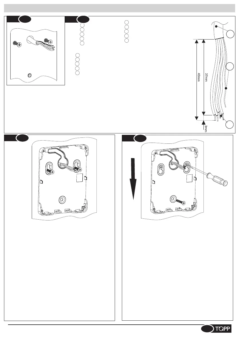
Fig.
9
Installazione selettore - Switch installation - Installation sélecteur - Instalación selector - Installation des Schalters
7
6
5
IT- 5 -Guaina
FR- 5 -Guaina
EN- 5 -Sheath
SP- 5 -Vaina
DE- 5 -Kabelmantel
IT- 6 -Cavo per schermatura
EN- 6 -Wire for shielding
DE- 6 -Abschirmkabel
SP- 6 -Cable para protección
FR- 6 -Câble pour blindage
SP- 7 -4 cables sec.mín.0.3mm²-máx 0.5mm²
IT- 7 -Num.4 cavi sez.min.0.3mm²-max 0.5mm²
FR- 7 -4 câbles sect. min. 0,3 mm ²- max. 0,5 mm ²
EN- 7 -4 wires with a min. cross section of 0.3sq.mm.-max 0.5sq.mm
DE- 7 -4 Kabel Durchm.min.0.3mm²-max. 0.5mm²
DE- Abisolierung Installateurkabel. Wenn ein abgeschirmtes Kabel verwendet wird, die Abschirmung so
abschneiden, dass sie nicht aus der Ummantelung herausragt.
EN- Strip the installer wire. If a shielded cable is used, cut the shielding so that it does not protrude from the
sheath.
SP- Cable instalador pelado. En caso de utilización de cable blindado, cortar la protección de forma que
no sobresalga de la vaina.
IT- Spellatura cavo installatore. In caso di utilizzo di cavo schermato, tagliare la schermatura in maniera
che non fuoriesca della guaina.
FR- Dénudage câble installateur En cas d'utilisation d'un câble blindé, couper le blindage de manière qu'il
ne sorte pas de la gaine.
FR-Placer la base du sélecteur en faisant passer la tête des
vis à travers la zone la plus large de la fente. Déplacer vers le
bas de la base jusqu'au posage des vis supérieures dans la
fente dédiée. Voir Fig. 9.
SP- Colocar la base del selector haciendo pasar la cabeza de
los tornillos a través de la zona más amplia de la ranura.
Desplazar hacia abajo la base hasta la colocación de los
tornillos superiores en la ranura específica. Véase Fig.9.
EN- Position the base of the switch by sliding the head of the
screws through the wide part of the slot. Move the base
downward until it rests on the upper screws in their slot. See
Fig.9
DE-Die Basis des Schalters positionieren, dabei die
Schraubenköpfe durch den breiteren Bereich der Öse
stecken. Die Basis nach unten verschieben, bis die
Schrauben im oberen Bereich der Ösen fest sitzen. Siehe
Abb. 9
IT- Posizionare la base del selettore facendo passare la testa
delle viti attraverso la zona più ampia dell’asola.Spostare
verso il basso la base fino al posaggio delle viti superiori
nell’asola dedicata. Vedi Fig.9
DE- Die oberen Schrauben festziehen. Die untere Schraube
eindrehen und festziehen. Hinweis: Es wird empfohlen, die
Schraube per Hand festzuziehen, da die Basis eine
verringerte Anschlagstärke hat.
IT- Fissare le viti superiori. Inserire e fissare la vite inferiore.
N.B Si consiglia il fissaggio manuale in quanto la base ha uno
spessore di battuta ridotto.
N.B. On conseille une fixation manuelle, dans la mesure où la
base a une épaisseur de butée limitée.
Note: We recommend manual fastening as the base has a
reduced thickness for tightening.
SP- Fijar los tornillos superiores. Introducir y fijar el tornillo
inferior.
N.B. Se aconseja la fijación manual ya que la base tiene un
grosor de tope reducido.
EN- Tighten the upper screws. Insert and tighten the lower
screw.
FR- Serrer les vis supérieures. Insérer et fixer la vis
inférieure.
4
Fig.
6
Fig.
7
 Loading...