DISASSEMBLE THE ORIGINAL DRAWBAR
1. Put on safety eyewear.
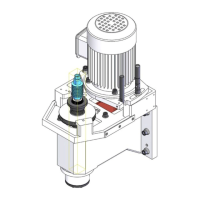
2. While using one hand to hold the spindle lock arm, use the other to remove the spindle lock arm pivot screw
with a 5 mm hex wrench.
Figure 5: Spindle lock arm pivot screw removed from the original drawbar assembly.
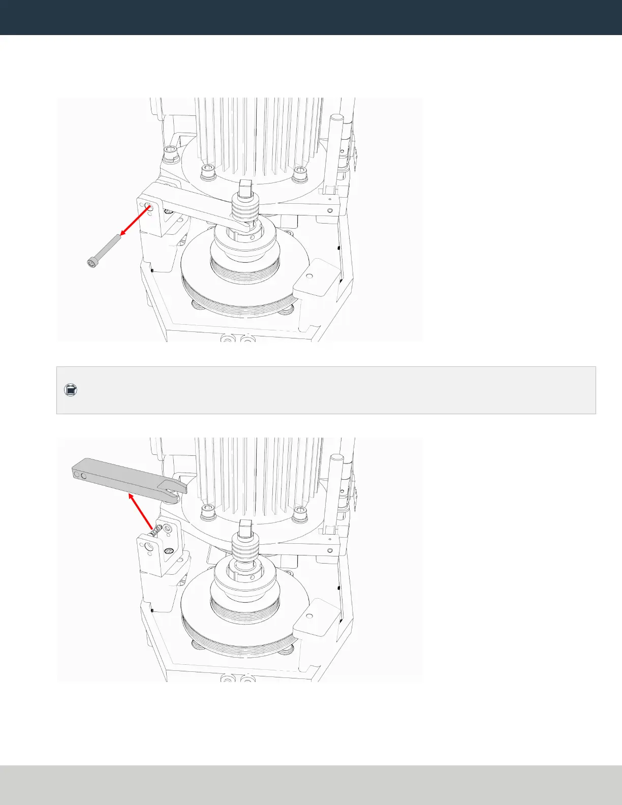
Note: The spindle lock arm assembly contains spring-loaded hardware, which could quickly
become loose.
3. Carefully remove the spindle lock arm.
Figure 6: Spindle lock arm removed from the original drawbar assembly.
Page 11
©Tormach® 2021
Specifications subject to change without notice.
tormach.com
TD10705: Installation Guide: BT30 Spindle Upgrade Kit for 1100M+ (0521A)