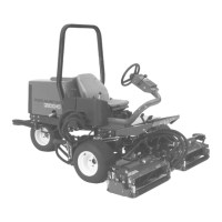
2
AdjustingtheControl-Arm
Position
NoPartsRequired
Procedure
Thecontrol-armpositioncanbeadjustedforthe
operatorscomfort.
1.Loosenthe2boltssecuringthecontrolarmto
theretainingbracket(Figure3).
g004152
Figure3
1.Controlarm
3.Bolts
2.Retainingbrackets
2.Rotatethecontrolarmtothedesiredposition
andtightenthe2bolts.
3
InstallingtheCuttingUnits
Partsneededforthisprocedure:
1
Rightfronthoseguide
1
Leftfronthoseguide
Procedure
1.Removethereelmotorsfromtheshipping
brackets.
2.Removetheshippingbracketsanddiscard.
3.Removethecuttingunitsfromthecartons.
Assembleandadjustasdescribedinthecutting
unitOperator'sManual.
4.Makesurethecounterweight(Figure4)is
installedtotheproperendofthecuttingunitas
describedinthecuttingunitOperator'sManual.
g003320
Figure4
1.Counterweight
5.Mounttheturf-compensationspringtothesame
sideofthecuttingunitasthereel-drivemotor.
Repositiontheturf-compensationspringas
follows:
Note:Allcuttingunitsareshippedwiththe
turf-compensationspringmountedtotheright
sideofthecuttingunit.
A.Removethe2carriageboltsandnuts
securingtherodbrackettothecutting-unit
tabs(Figure5).
11