g031996
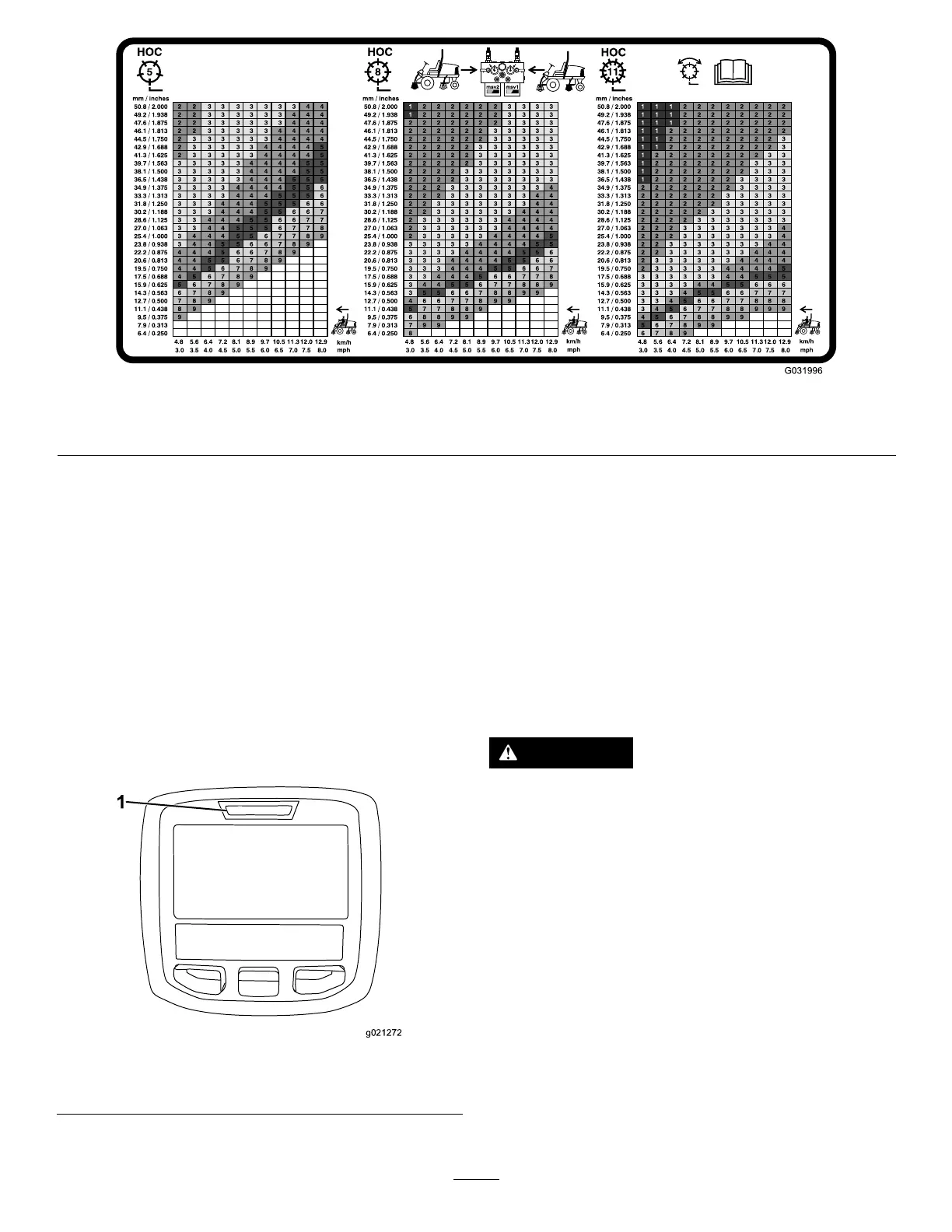
Figure32
7inch(177.8mm)ReelSpeedChart
Understandingthe
DiagnosticLight
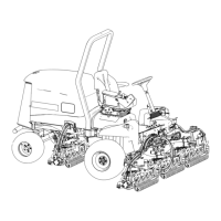
Themachineisequippedwithadiagnosticlight
whichindicatesiftheelectroniccontrollersensesan
electronicmalfunction.Thediagnosticlightislocated
ontheInfoCenter,abovethedisplayscreen(Figure
33).Whenthemachineisfunctioningproperlyand
thekeyswitchismovedtotheON/RUNposition,the
diagnosticlightturnsonbrieytoindicatethelightis
workingproperly.Whenamachineadvisorymessage
isdisplayed,thelightilluminateswhenthemessageis
present.Whenafaultmessageisdisplayed,thelight
blinksuntilthefaultisresolved.
g021272
Figure33
1.Diagnosticlight
CheckingtheInterlock
Switches
Thepurposeoftheinterlockswitchesistopreventthe
enginefromcrankingorstartingunlessthetraction
pedalisintheNEUTRALposition,theEnable/Disable
switchisintheDISABLEposition,andtheLower
Mow/RaisecontrolisintheNEUTRALposition.In
addition,theengineshouldstopwhenthetraction
pedalispressedwithoperatorofftheseatorifthe
parkingbrakeisleftengaged.
CAUTION
Ifsafetyinterlockswitchesaredisconnected
ordamagedthemachinecouldoperate
unexpectedlycausingpersonalinjury.
•Donottamperwiththeinterlockswitches.
•Checktheoperationoftheinterlock
switchesdailyandreplaceanydamaged
switchesbeforeoperatingthemachine.
VerifyingtheInterlock-Switch
Function
ServiceInterval:Beforeeachuseordaily—Check
theoperationoftheinterlock
switches.
1.Parkthemachineonalevelsurface,lowerthe
cuttingunits,stoptheengine,andengagethe
parkingbrake.
29