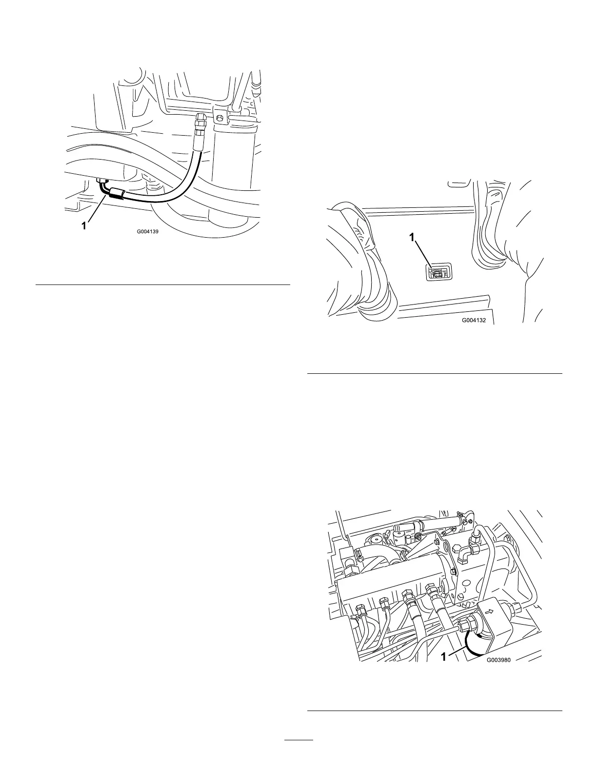
2.Placealargedrainpanunderthettingsecured
tothebottomofthehydraulic-uidreservoir
(Figure65).
g004139
Figure65
1.Hose
3.Disconnectthehosefromthebottomofthe
ttingandletthehydraulicuidowintothe
drainpan.
4.Installthehosewhenhydraulicuidstops
draining.
5.Fillthereservoirwithapproximately56.7L(15
USgallons)ofhydraulicuid;refertoChecking
theHydraulic-FluidLevel(page48)
Important:Useonlythehydraulicuids
specied.Otheruidscouldcausesystem
damage.
6.Installthereservoircap.
7.Starttheengineanduseallofthehydraulic
controlstodistributehydraulicuidthroughout
thesystem.Alsocheckforleaks.
8.Stoptheengine.
9.Checkthelevelofthehydraulicuidandadd
enoughtoraiseleveltotheFullmarkonthe
dipstick.
Important:Donotoverllthereservoir.
ReplacingtheHydraulic
Filters
ServiceInterval:Every800hours(Ormoreoftenif
theservice-intervalindicatorisin
theredzone).
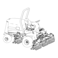
Thehydraulicsystemisequippedwitha
service-intervalindicator(Figure66).Withtheengine
runningatoperatingtemperature,viewtheindicator,it
shouldbeinthegreenzone.Whentheindicatorisin
theredzone,changethehydrauliclters.
g004132
Figure66
1.Hydraulic-lter-restrictionindicator
Important:Useofanyotherltersmayvoidthe
warrantyonsomecomponents.
1.Positionthemachineonalevelsurface,lower
thecuttingunits,stoptheengine,engagethe
parkingbrake,andremovethekeyfromthe
ignitionswitch.
2.Cleantheareaaroundtheltermountingarea
andplaceadrainpanunderlter(Figure67and
Figure68).
g003980
Figure67
1.Hydrauliclter
49