A.Installthebelt-driveassemblyusingthe
previouslyremovedbolts,andensurethat
thesideplaterotatesfreely(Figure6).
B.Installthelowerpulleyontothereeldrive
shaft,securingitwith2setscrewsontothe
keyontheshaft(Figure5).
C.Torquethesetscrewsto7to7.5N·m(60
to65in-lb).
D.Installthedrivebeltandtensionitas
describedinthetractionunitOperator’s
Manual.
13.Securethegroomerdrivegeartothereelshaft
ontherightsideofthereel(Figure10),and
torqueto170N·m(125ft-lb).
Note:Theuseofanimpactgunisnotenough
toensureproperinstallation.Failingtoproperly
torquethedrivepulleycanresultintheassembly
unscrewingitselfduringoperation.
14.Installandsecuretheidlergears(Figure10)and
torquethecapscrewsto13.5N·m(120in-lb).
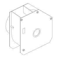
15.Installtheidlertensionspring(Figure12).
g028142
Figure12
1.Tensionspring3.Measurehere.
2.Eccentricstop
16.Withtheidlergearengaged,useasparkplug
gappingtooltocheckthatthereisa0.38to0.45
mm(0.015to0.018inch)gapbetweenthedriver
andxedidlergear(Figure12).
Note:Youcanadjustthegapbyrotatingthe
eccentricstopfortheidlergear.
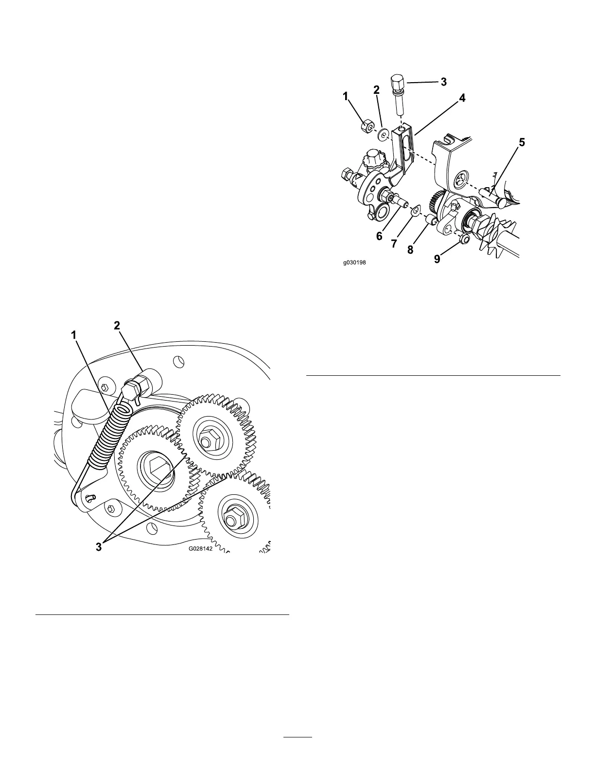
InstallingtheAdjusterArms
1.Installthebushingintheholeintheright
groomer-driveassembly(Figure13).
g030198
Figure13
1.Nut
6.Rodendofthe
height-of-cutassembly
2.Specialwasher7.Springwasher
3.Height-of-cutscrew
8.Bushing
4.Adjuster-armassembly9.Locknut
5.Plowbolt
2.Threadtheheight-of-cutadjustingscrewintothe
topoftherightadjuster-armassembly(Figure
13).
3.Installthespringwasherontotherodendofthe
height-of-cutarmassembly(Figure13).
4.Installtherightadjuster-armassemblytothe
cuttingunitsideplateusingaplowbolt,nut,and
specialwasher(Figure13).
Note:Makesurethattherodendofthe
height-of-cutarmassemblyslidesintothe
bushingintheholeinthegroomerdrive
assembly.
5.Securetheadjuster-armassemblyrodendto
thegroomerdriveassemblywiththelocknut
(Figure13).
Note:Donotovertightenthelocknut.The
washershouldbecompressedbutthearmmust
befreetopivot.
6