Step
1
Removing the Shipping
Bracket and Shipping
Washers
No Parts Required
Procedure
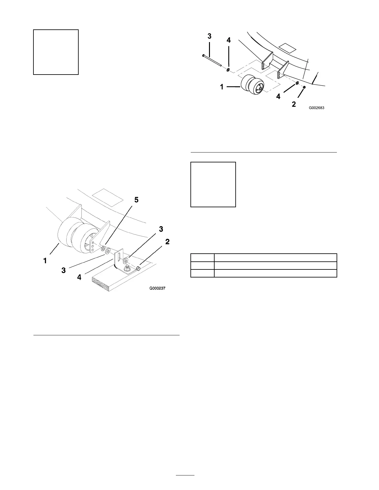
1. R emo v e the center g ag e wheel n ut, 2 larg e
w ashers , angle brac k et and 1 small w asher
( Figure 3 ). Discard the 2 larg e w ashers and the
angle brac k et.
Figure 3
1. Center Gage Wheels and
Spacer
4. Angle bracket-discard
2. Nut
5. Small washer
3. Large washer-discard
2. Install the center g ag e wheels with the
previously remo v ed bolt, spacer , small w asher ,
and n ut ( Figure 4 ).
Figure 4
1. Center Gage Wheels and
Spacer
4. Washer
2. Nut 5. Spacer
3. Bolt
Step
2
Installing the Handle
Assembly
Parts needed for this step:
1
Handle assembly
4
Flanged bolt, (3/8 x 1 inch)
4
Flange nut, (3/8 inch)
Procedure
1. Align handle with upper mounting holes in
rear frame ( Figure 5 ).
2. Secure the handle at eac h upper mounting hole
with a flang e bolt (3/8 x 1 inc h) and flang e n ut
( Figure 5 ).
3. Select the lo w position for the lo w er mounting
hole ( Figure 5 ).
4. Secure the handle at eac h lo w er mounting hole
with a flang e bolt (3/8 x 1 inc h) and flang e n ut
( Figure 5 ).
Note: T he handle position can be adjusted to
matc h the operator’ s height preference .
12