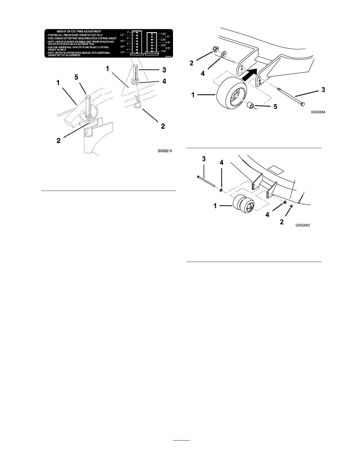
Figure 23
1. Carrier Frame
4. Spacers
2. Hairpin Cotter
5. Back height-of-cut post
3. Front height-of-cut post
Adjusting the Gage Wheels
T he g ag e wheels need to be adjusted in the proper
hole location for eac h height-of-cut position.
T here needs to be 3/8 inc h (10 mm) minim um
clearance abo v e the g round.
1. After adjusting height-of-cut, c hec k the g ag e
wheels so that there is a minim um of 3/8 inc h
(10 mm) clearance abo v e the g round ( Figure 24
and Figure 25 ).
2. If adjustment is needed, remo v e the bolt,
w ashers and n ut ( Figure 24 and Figure 25 ).
3. Select a hole position so the g ag e wheels are a
minim um of 3/8 inc h (10 mm) off the g round
( Figure 24 and Figure 25 ).
4. Install the bolt, w ashers and n ut ( Figure 24 and
Figure 25 ).
Figure 24
1. Gage Wheels 4. Washer
2. Nut 5. Spacer
3. Bolt
Figure 25
1. Center Gage Wheels and
spacer
3. Bolt
2. Nut
4. Washer
Adjusting the Handle Height
T he handle position can be adjusted to matc h the
operator’ s height preference .
1. R emo v e hair pin cotter , w asher and clevis pin
securing control rod fitting to idler brac k et
( Figure 26 ).
25