operating position. Disconnect the spark plug
wire(s) from the spark plug(s).
3. Adjust the tire pressure in all tires to
specifications on pag e .
4. Chec k that the blades and spindle shafts are
not bent. R efer to Chec king for Bent Blades .
5. Set the height-of-cut to the 4 inc h (101.6 mm)
position. R efer to Adjusting the Height-Of-Cut
in Operation , pag e 19 .
6. P erfor m the ste ps in the follo wing sections
F rame Set Up , Chec king F ront-to-R ear Pitc h,
and Chec king Side-to-Side Lev eling .
Adjusting the Frame
Checking the Carrier Frame and Deck
Alignment
1. Diseng ag e the PTO and set the parking brak e .
2. Stop the engine , remo v e the k ey , and w ait for
all mo ving par ts to stop before lea ving the
operating position.
3. Place a long straight edg e on top of the engine
dec k as sho wn in Figure 58 .
Figure 58
1. Carrier Frame
4. Location A, 1-5/16 inch (33
mm) ±1/4 inch (6 mm)
2. Top of engine deck 5. Straight edge
3. Carrier frame mounting
bolts
6. Carrier frame cross tube
4. At the car rier frame cross tube , measure
the height at location A ( Figure 58 ). T his
measurement m ust be 1-5/16 inc h (33 mm),
plus or min us a 1/4 inc h (6 mm).
5. If the height at location A is not cor rect,
adjustment is needed.
6. Loosen the car rier frame mounting bolts on
both sides of the mac hine ( Figure 58 ).
7. Align the car rier frame and engine dec k to
matc h 1-5/16 inc h (33 mm), plus or min us a
1/4 inc h (6 mm) at location A ( Figure 58 ).
8. Tighten the car rier frame mounting bolts on
both sides of the mac hine .
Checking the Engine Deck Height
1. Diseng ag e the PTO and set the parking brak e .
2. Stop the engine , remo v e the k ey , and w ait for
all mo ving par ts to stop before lea ving the
operating position.
3. Adjust the tire pressure in all tires to
specifications on pag e .
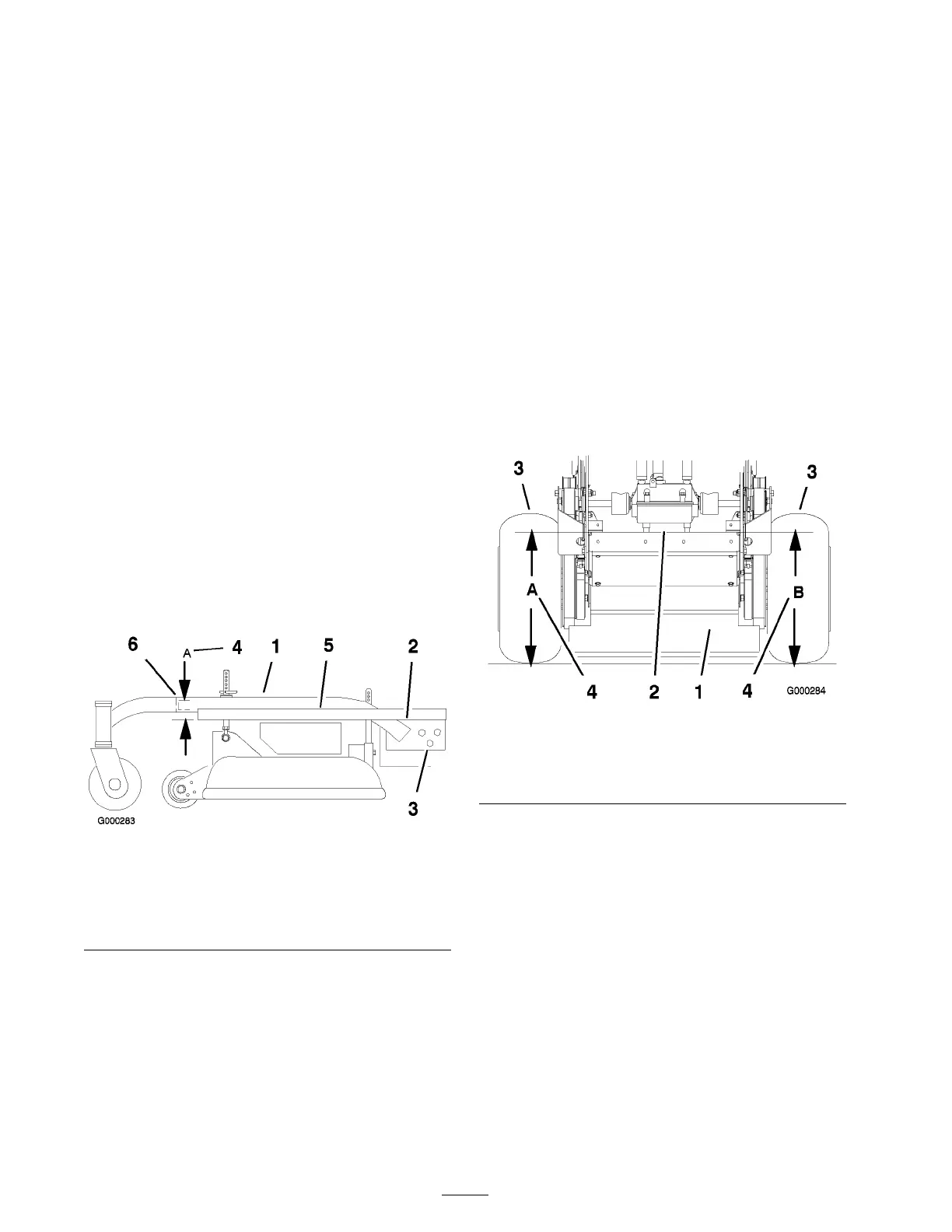
4. Measure engine dec k height at location A
( Figure 59 ).
Figure 59
1. Back view of machine
3. Tires
2. Top of engine deck 4. Same height at locations A
and B
5. Measure engine dec k height at location B
( Figure 59 ).
6. If the height at location A and B are not the
same , c hang e tire pressure slightly to mak e
them the same .
Checking Carrier Frame Front-to-Rear
Pitch
T he car rier frame m ust ha v e a pitc h of a 1/4 inc h
(6 mm) o v er the length of 24 inc hes (61 cm) on
the car rier frame ( Figure 60 ).
1. Measure out 24 inc hes (61cm) on the car rier
frame ( Figure 60 ).
42