5. Disconnect clutc h wire connector from wire
har ness .
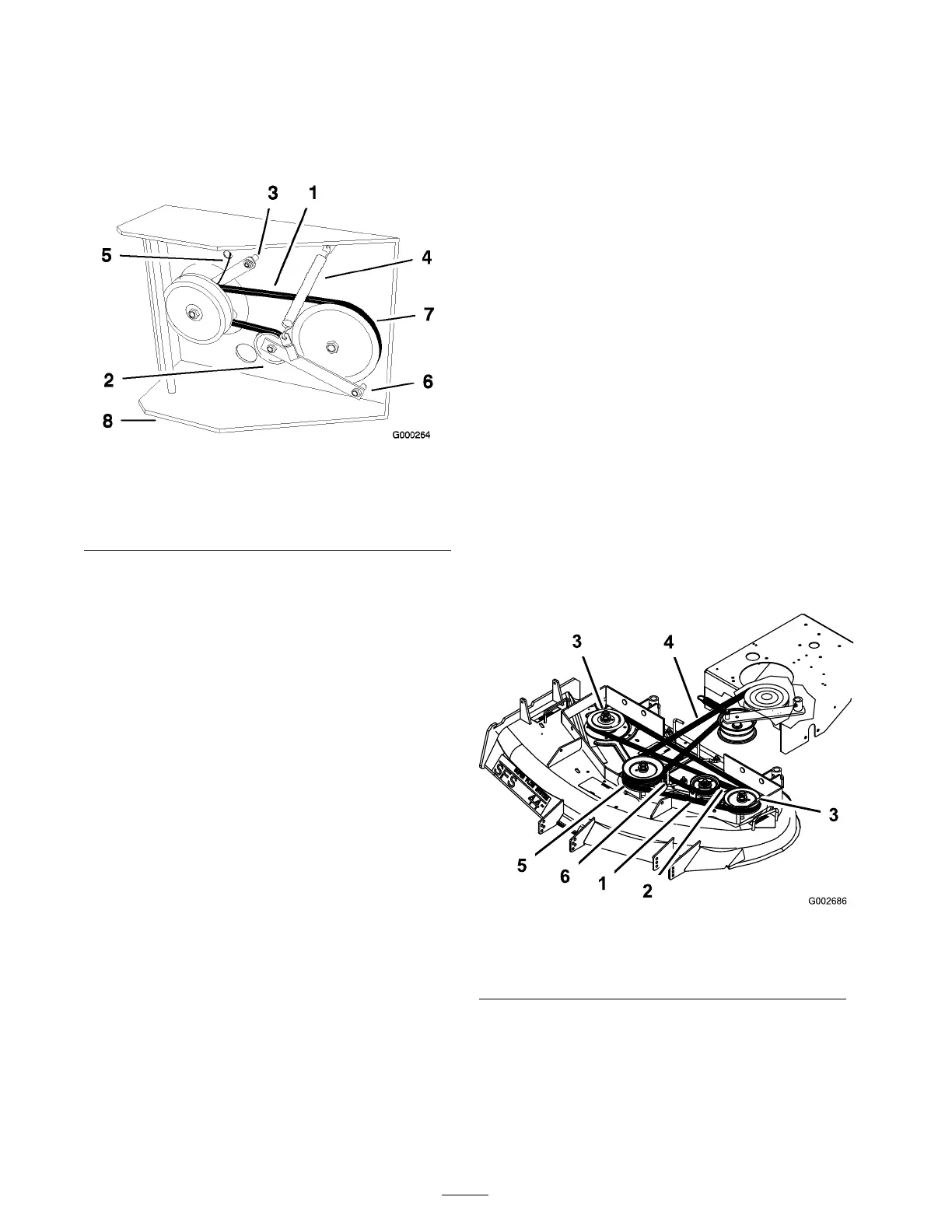
6. Disconnect clutc h retainer from the engine
dec k ( Figure 50 ).
Figure 50
1. Transmission belt 5. Clutch wire connector
2. Idler pulley 6. Pivot bolt
3. Clutch retainer 7. Drive pulley
4. Tension spring
8. Engine deck
7. Unhook tension spring from side of frame
( Figure 50 ).
8. Loosen pi v ot bolt enough to remo v e traction
belt from the dri v e pulley and clutc h.
9. Install new belt around clutc h and dri v e pulley .
10. T or que pi v ot bolt to 35-40 ft-lb (47-54 N·m).
Install tension spring betw een idler ar m and
frame brac k et ( Figure 50 ).
11. Install clutc h retainer to the engine dec k
( Figure 50 ).
12. Connect clutc h wire connector to wire har ness .
13. Install PTO dri v e belt.
Replacing the Mower Belt
Squealing when the belt is rotating, blades slipping
when cutting g rass , fra yed belt edg es , bur n marks
and crac ks are signs of a w or n dec k belt. R e place
the dec k belt if any of these conditions are evident.
1. Diseng ag e the PTO and set the parking brak e .
2. Stop the engine , remo v e the k ey , and w ait for
all mo ving par ts to stop before lea ving the
operating position.
3. R emo v e the knobs/r ubber w ashers holding
the car rier frame co v er and remo v e the car rier
frame co v er .
4. R emo v e the knobs/r ubber w ashers holding
the belt co v er to the cutting unit and remo v e
the belt co v er .
5. R emo v e the PTO dri v e belt. R efer to R e placing
the PTO Dri v e Belt in Belt Maintenance ,
pag e 37 .
6. Disconnect the idler ar m spring to reliev e
tension on the idler ar m and idler pulley , then
remo v e the w or n mo w er dec k belt ( Figure 51 ).
7. Install the new mo w er dec k belt around the
tw o outside spindle pulleys , the idler pulley ,
and in the lo w er g roo v e of the double spindle
pulley ( Figure 51 ).
8. Connect the idler ar m spring ( Figure 51 ).
9. Install the PTO dri v e belt. R efer to R e placing
the PTO Dri v e Belt in the Belt Maintenance ,
pag e 37 .
10. Adjust the belt guide an 1/8 inc h (3 mm) from
the belt ( Figure 51 ).
11. Install the belt co v er onto the cutting unit, then
install and tighten the knobs/r ubber w ashers .
12. Install the car rier frame co v er onto the cutting
unit, then install and tighten the knobs/r ubber
w ashers .
Figure 51
1. Mower deck belt 4. PTO Drive Belt
2. Idler arm spring 5. Center spindle pulley
3. Outside pulley 6. Belt guide
Replacing the PTO Drive Belt
Squealing when the belt is rotating, blades slipping
when cutting g rass , fra yed belt edg es , bur n marks
and crac ks are signs of a w or n dri v e belt. R e place
the dri v e belt if any of these conditions are evident.
38