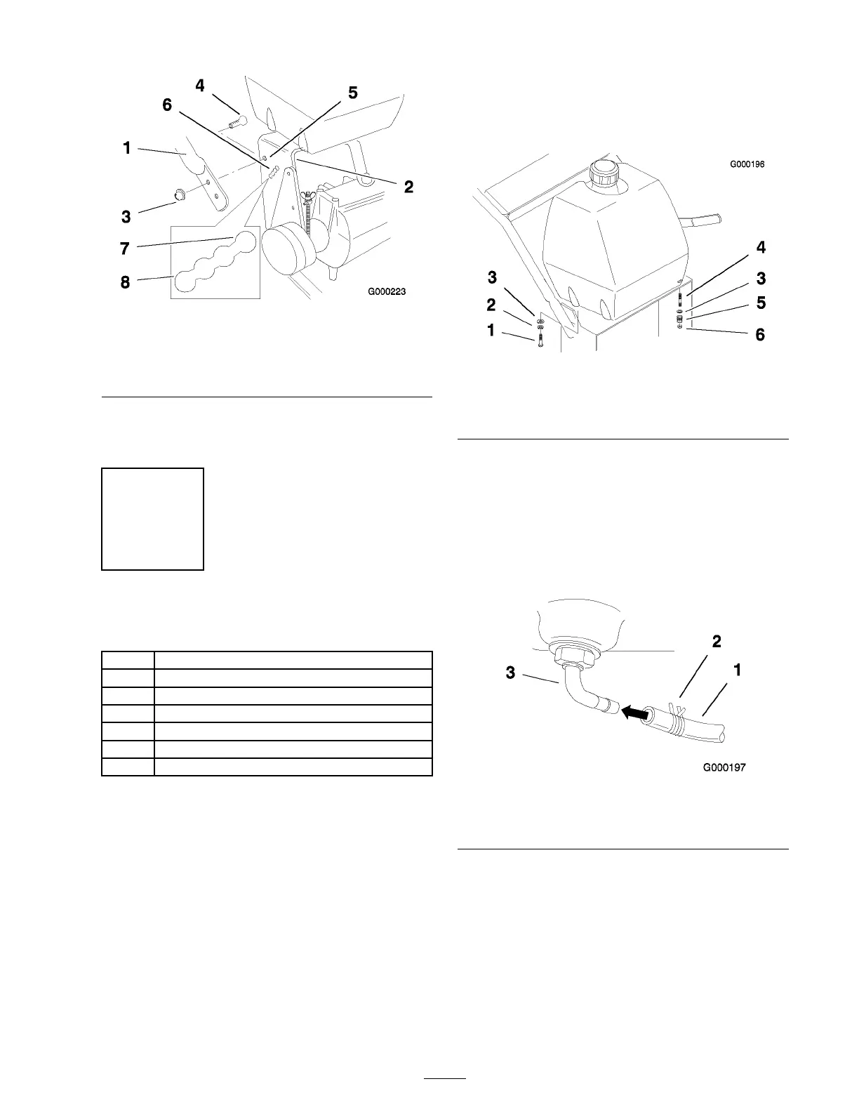
Figure 5
1. Upper handle 5. Upper mounting hole
2. Rear frame 6. Lower mounting holes
3. Flange nut, (3/8 inch)
7. Low position
4. Flange bolt, (3/8 x 1 inch)
8. High position
Note: Handle assembly m ust be installed
before fuel tank is installed.
Step
3
Installing the Fuel Tank
Parts needed for this step:
1
Fuel tank with studs installed
2
Bolt, (5/16 x 7/8 inch)
2
Lock nut, (5/16 inch)
4
Washer, (5/16 inch)
1
Hose clamp
2
Lock washer, (5/16 inch)
2
Spring
Procedure
1. Align the fuel tank with the top of the rear
frame ( Figure 6 ).
2. Secure the right side of the fuel tank to the
rear frame with 2 bolts (5/16 x 7/8 inc h), loc k
w ashers (5/16 inc h) and w ashers (5/16 inc h)
( Figure 6 ).
3. Secure the left side of the fuel tank to the
rear frame with 2 studs , w ashers (5/16 inc h),
springs , and loc kn uts (5/16 inc h) ( Figure 6 ).
Note: Tighten left side of the fuel tank until
it is completely tight and then unscrew loc kn ut
one full tur n. T his will allo w the spring to
w ork.
Figure 6
1. Bolt, 5/16 x 7/8 inch 4. Stud
2. Lock washer, (5/16 inch)
5. Spring
3. Washer, (5/16 inch)
6. Locknut
Note: R emo v e the plastic cap from the fuel
fitting before installing the fuel line .
4. Slide the hose clamp onto the fuel line
( Figure 7 ).
5. Push the fuel line onto the fuel tank connection
and secure it with a hose clamp ( Figure 7 ).
Figure 7
1. Fuel line 3. Fuel tting
2. Hose clamp
13