Figure52
1.Bolt
2.Controlpanel
4.MovethecontrollevertotheNEUTRALpositionbut
notlocked(Figure54).
5.Pulltheleverbackuntiltheclevispin(onanarm
abovethepivotshaft)contactstheendoftheslot(just
beginningtoputpressureonthespring)asshownin
Figure53.
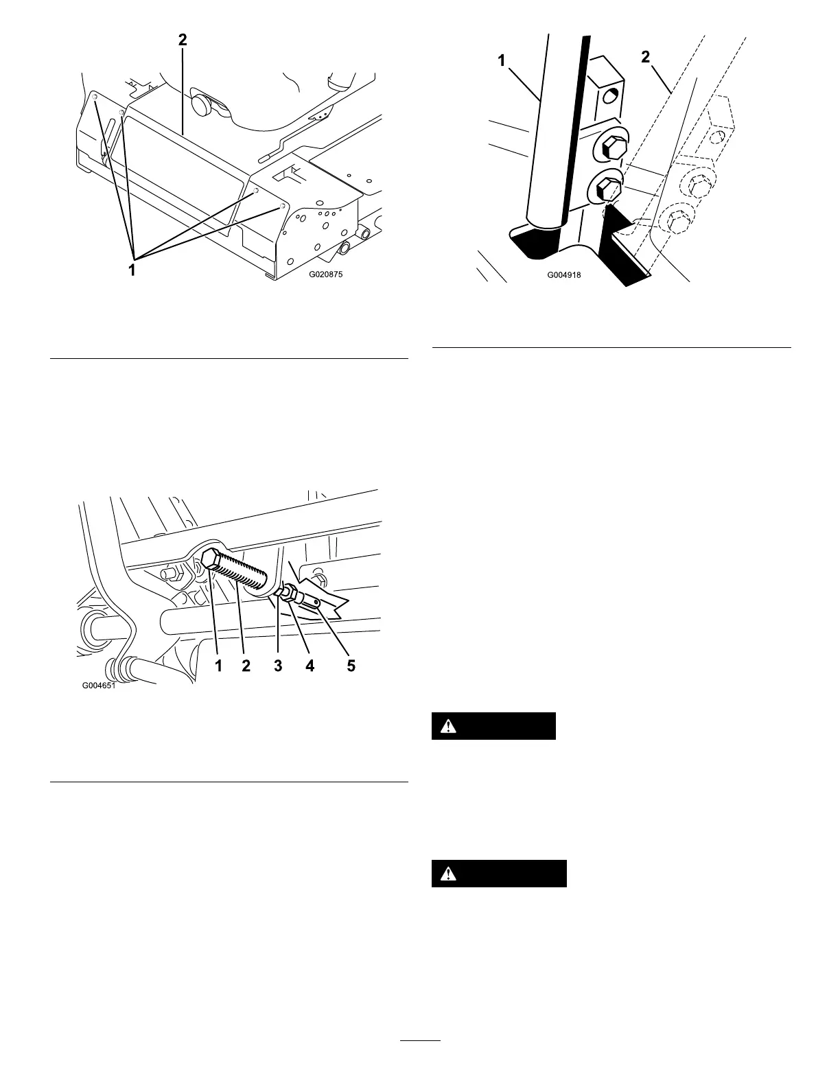
Figure53
1.Clevispin
4.Adjustmentbolt
2.Slot
5.Yoke
3.Jamnut
6.Checkwherethecontrolleverisrelativetonotchinthe
console(Figure54).
Note:Thecontrollevershouldbecentered,allowing
levertopivotoutwardtotheNEUTRAL-LOCKposition.
Figure54
1.NEUTRALposition2.NEUTRAL-LOCKposition
7.Ifadjustmentisneeded,loosenthenutandjamnut
againsttheyoke(Figure53).
8.Applyingslightrearwardpressureonthe
motion-controllever,turntheheadoftheadjustment
boltintheappropriatedirectionuntilthecontrollever
iscenteredintheNEUTRAL-LOCKposition(Figure53).
Note:Rearwardpressureontheleverkeepsthepin
attheendoftheslotandallowtheadjustmentboltto
movethelevertotheappropriateposition.
9.Tightenthenutandjamnut(Figure53).
10.Repeatsteps4through9fortheothercontrollever.
11.Installthefrontpanel.
AdjustingtheTractionDrive
forNeutral
Makethisadjustmentwiththedrivewheelsturning.
DANGER
Mechanicalorhydraulicjacksmayfailtosupport
themachineandcauseaseriousinjury.
•Usejackstandswhensupportingthemachine.
•Donotusehydraulicjacks.
WARNING
Theenginemustberunningtoperformthis
adjustment.Contactwithmovingpartsorhot
surfacesmaycausepersonalinjury.
Keephands,feet,face,clothing,andotherbody
partsawayfromrotatingparts,mufer,andother
hotsurfaces.
46