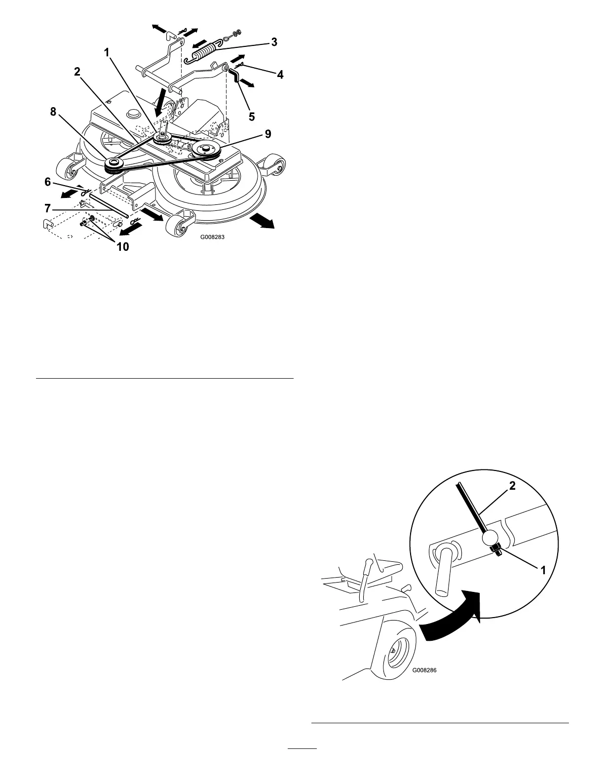
Figure39
1.Idlerpulleyandidlerarm
assembly
7.Frontpin
2.V-belt8.Enginepulley
3.Engagementspring9.V-beltpulley
4.Rearhairpinclips10.FrontsuspensionM12
nuts
5.Rearpins11.Bag-on-demandassembly
(notshown)
6.Fronthairpinclips
Note:Thebag-on-demandassemblyisnotshown
forthepurposeofclarity.
9.Disconnectthespringfromtheengagementlever
(Figure39).
10.Releasethemowerfromthetunnelbyliftingthe
tunneloffthe2weldedpinsandpullingthetunnel
rearwardapproximately4inches(10cm).Securethe
tunneltopreventitfromfallingdown.
11.Removethehairpinclipsfromthe2rearpinsand
removethepins(Figure39).
Note:Youmayneedaplierstopulloutthesecond
pin.
12.Removethehairpinclipfromthefrontpinand
removethepin(Figure39).
13.RemovetheV-beltfromtheenginepulley
(Figure39).
14.Slidethemoweroutfrombeneaththemachine.
InstallingtheMower
ReversetheprocedureforRemovingtheMower.
AdjustingtheHeight
AdjustmentCableRod
Assembly
ServiceInterval:Every100hours/Yearly(whichever
comesrst)—Checkthefront-to-rear
bladeslope.(Alsocheckitwhenever
youinstallthemower.)
Beforeyouchecktheslope,inatethefrontandrear
tirestotherecommendedairpressure;refertoChecking
theTirePressure.Ifthefrontofthemowerisnotwithin
4to11mm(1/8to3/8inch)lowerthantherearofthe
mower,adjustthebladeslope.
1.Parkthemachineonalevelsurface.
2.Disengagetheblades(PTO).
3.Settheparkingbrake.
4.Stoptheengineandwaitforallmovingpartstostop.
5.Removetheignitionkey.
6.Disconnectthewirefromthesparkplug.
7.Movethelowerpinofthefrontadjustment
suspensionintothebottompositionoftheslotted
holesbyadjustingthe2nuts(M12)onthefront
suspension(Figure39).
8.Movetheheight-of-cutlevertoposition1.
Note:Thefrontmowergaugewheelsmustreston
theground.
9.AdjusttheM8locknutattheendoftheheight
adjustmentrodassemblyuntiltherodisslightlytaut
(Figure40).
Figure40
1.M8locknut2.Heightadjustmentrod
34