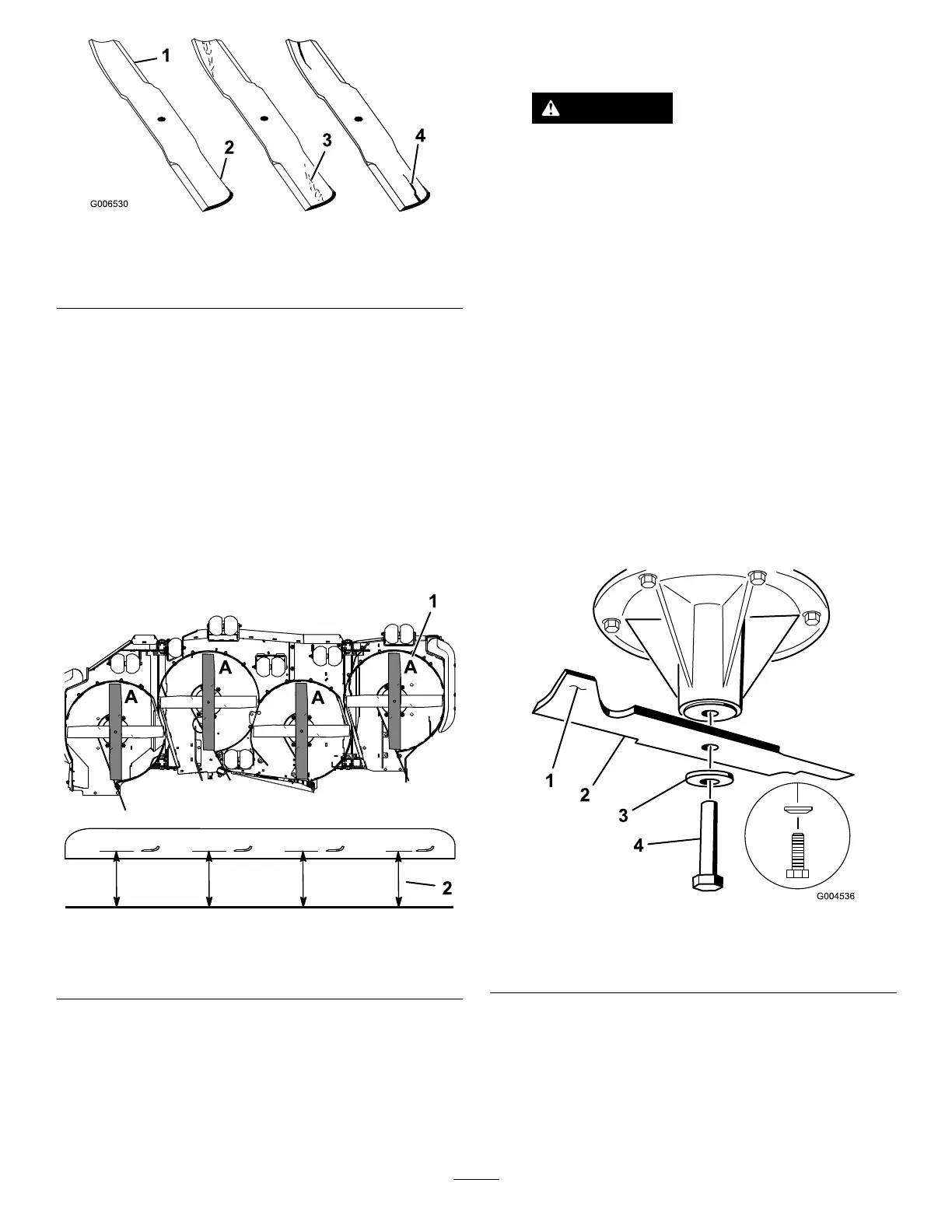
g006530
Figure76
1.Cuttingedge3.Wear/slotforming
2.Curvedarea4.Crack
CheckingforBentBlades
1.Disengagetheblade-controlswitch(PTO),move
themotion-controlleverstotheNEUTRAL-LOCK
position,andengagetheparkingbrake.
2.Shutofftheengine,removethekey,andwait
forallmovingpartstostopbeforeleavingthe
operatingposition.
3.Rotatethebladesuntiltheendsfaceforward
andbackward(Figure77).
4.Measurefromalevelsurfacetothecutting
edge,positionA,oftheblades(Figure77).
g243961
Figure77
1.PositionA
2.Measureherefromthe
bladetoahardsurface.
5.Rotatetheoppositeendsofthebladesforward.
6.Measurefromalevelsurfacetothecuttingedge
ofthebladesatthesamepositionasinstep4.
Note:Thedifferencebetweenthedimensions
obtainedinsteps4and5mustnotexceed3
mm(1/8inch).
Note:Ifthisdimensionexceeds3mm(1/8
inch),thebladeisbentandmustbereplaced.
DANGER
Abladethatisbentordamagedcould
breakapartandcouldseriouslyinjureor
killyouorbystanders.
•Alwaysreplacebentordamaged
bladewithanewblade.
•Neverleorcreatesharpnotchesin
theedgesorsurfacesofblade.
RemovingtheBlades
Replaceabladeifithitsanobject,ifthebladeisout
ofbalance,orifthebladeisbent.T oensureoptimum
performanceandcontinuedsafetyconformanceof
themachine,usegenuineTororeplacementblades.
Replacementbladesmadebyothermanufacturers
mayresultinnonconformancewithsafetystandards.
1.Holdthebladeendusingaragorathickly
paddedglove.
2.Removethebladebolt,curvedwasher,and
bladefromthespindleshaft(Figure78).
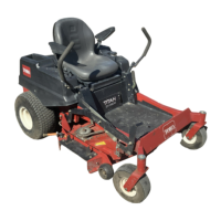
g004536
Figure78
1.Sailareaoftheblade3.Curvedwasher
2.Blade4.Bladebolt
60