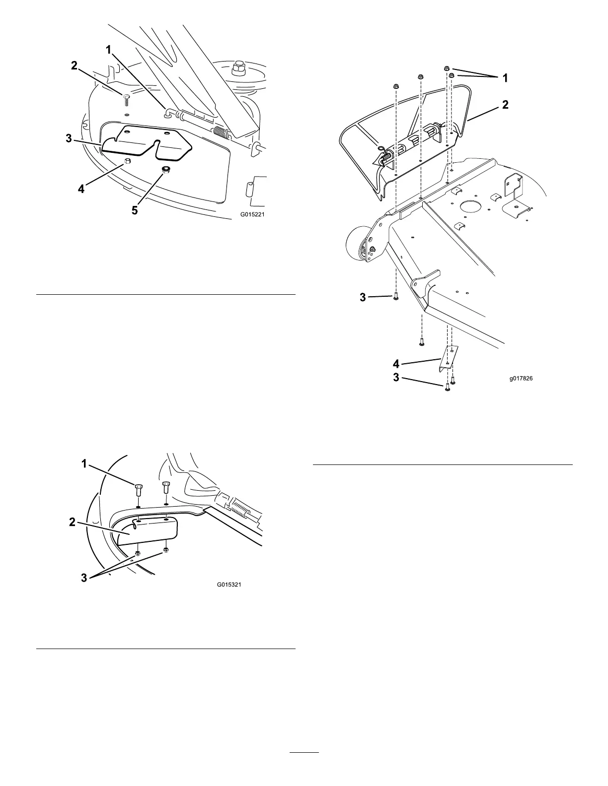
g015221
Figure 28
1. Pivot rod
4. Nut (5/16 inch)
2. Bolt 5. Locknut
3. Bagger-cutof f baf e
For Model 79392 Only
Note: Certain models have the cutof f baf e installed.
Proceed to the next procedure if a cutof f baf e is
installed.
Important: The cutoff bafe was shipped with the
machine as a loose part.
Install the cutof f baf e to the mower deck with 2 bolts
(5/16 x 3/4 inch) and 2 locknuts (5/16 inch). T orque
the fasteners to 7-9 N∙m (14-18 ft-lb).
g015321
Figure 29
1. Bolt (5/16 x 3/4 inch) 3. Locknut (5/16 inch)
2. Cutof f baf e
For Model 79393 Only
1. Remove the plate assembly that includes the
side discharge chute. Save this hardware and
assembly .
2. Remove the existing baf e under the right
side of the mower deck. Save the baf e and
hardware.
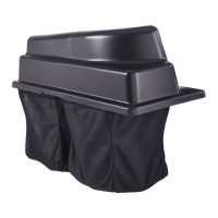
g017826
Figure 30
1. Flange nuts
3. Carriage bolts
2. Plate assembly with
discharge chute
4. Existing baf e
Note: When installing the existing baf e,
ensure the correct holes are used for each bolt.
3. Install the existing baf e with a carriage bolt
(5/16 x 1 inch) and nut (5/16 inch) from the
previously removed baf e.
4. Use a new bolt (5/16 x 1-3/8 inches) and ange
nut (5/16 inch) to secure the inside of the baf e.
17