20
Lynx® SmartHub Installation and User Guide
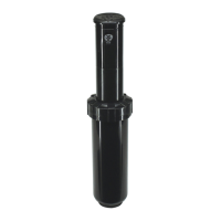
Layout 2 - Wired Lynx
The Field Interface Unit is attached to the SmartHub which is out in the field. Due to this distance (see note below), a
Surge Protection Unit (SPU) is necessary on both ends of the cable run.
FIU
SPU SPU
wireline
wireline to pedestal bypasses SPU
GDC-200
– +
HOME
%ADJUST START PAUSE/
RESUME
STOP SYSTEM
SETTINGS
MANUAL
WATERING
SCHEDULED
WATERING
DIAGNOSTICS STATION
SETTINGS
ON
12 34
ON
12 34
MENU
POWER
AUTO
+
-
LYNX
SmartHub 1
Wired Lynx
1 2 3
The Wireline connection is limited to about 9 miles.
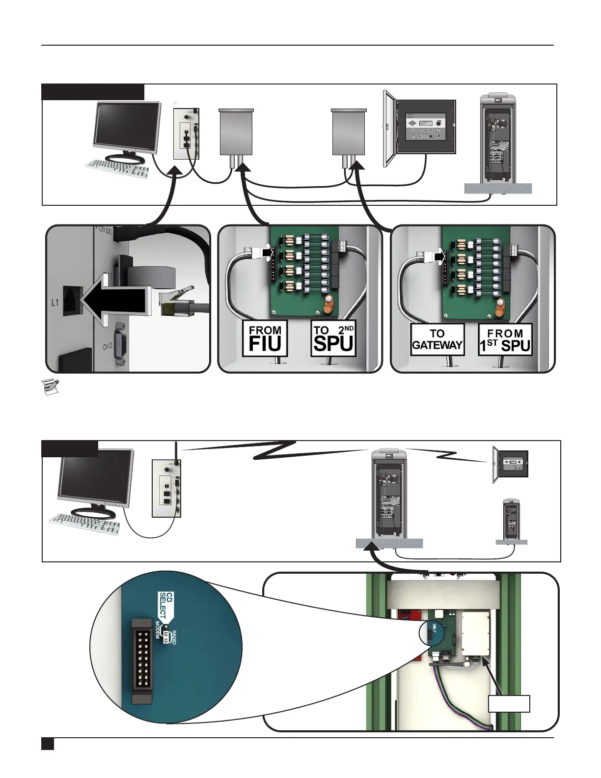
Layout 3 - Wireless
The Lynx SmartHub DEC-RS-1000-DR (digital radio and modem) communicates with the Lynx computer via radio. The
system is preconfigured at our production facility.
ON
12 34
ON
12 34
ON
1234
ON
1234
FIU
SmartHub 1
SmartHub 2
SmartHub 3
RF
GDC-200
– +
HOME
%ADJUST START PAUSE/
RESUME
STOP SYSTEM
SETTINGS
MANUAL
WATERING
SCHEDULED
WATERING
DIAGNOSTICS STATION
SETTINGS
MENU
POWER
AUTO
+
-
LYNX
Wireless
Radio
Set CD jumper for
method of communication.
• MODEM: jumper on left two pins.
• RADIO: jumper on right two pins.

 Loading...