EasyManuals Logo

Toshiba B-SA4T Series User Manual

Toshiba B-SA4T Series
58 pages
To Next Page IconTo Next Page
To Previous Page IconTo Previous Page
Page #17 background imageLoading...
Page #17 background image
INSTALLATION PROCEDURE FOR OPTIONAL EQUIPMENT EO15-33001A
2. Strip Module
2- 9
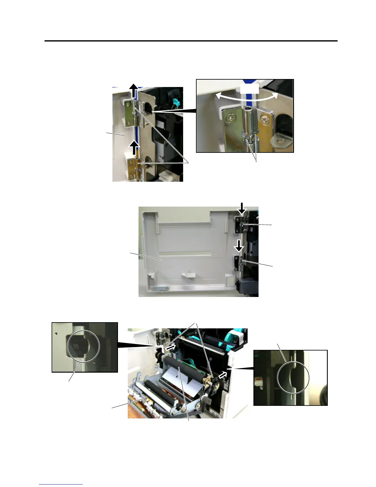
2. Open the Front Cover wider. Remove the Front Cover by lifting it to disengage the hinge pins from the
hinge. The Front Cover cannot be removed unless it is opened at an angle of over 100 degrees as the
stoppers of the hinge prevent disengagement.
3. Mount the strip Module Cover by inserting the hinge pins into the hinges.
4. Fit the Shaft Holders of the Backing Paper Feed Roller into the cuts of the printer.
Front Cove
r
Hinge
100°
Stopper
Hinge
Hinge
Strip Module Cove
r
Shaft Holder
Strip Uni
t
Cut
Cut
Backing Paper Feed Roller

Other manuals for Toshiba B-SA4T Series

Questions and Answers:

Question and Answer IconNeed help?

Do you have a question about the Toshiba B-SA4T Series and is the answer not in the manual?

Toshiba B-SA4T Series Specifications

General IconGeneral
Print TechnologyThermal Transfer / Direct Thermal
Print SpeedUp to 152.4 mm/sec (6 ips)
Max Print Width104 mm (4.09")
Resolution300 dpi
ConnectivityUSB 2.0
Optional InterfacesWireless LAN
BarcodesUPC/EAN/JAN, Code 39, Code 93, Code 128, EAN 128, NW7, Industrial 2 of 5, Postnet, RM4SCC, KIX-Code
2D CodesData Matrix, PDF417, QR Code, Maxi Code, Micro PDF417, Aztec Code
Media Thickness0.06 – 0.19 mm
Media Roll DiameterMax. 127 mm
Ribbon LengthUp to 300 m
Weight15 kg

Related product manuals