EasyManuals Logo

Toshiba B-SA4T Series User Manual

Toshiba B-SA4T Series
58 pages
To Next Page IconTo Next Page
To Previous Page IconTo Previous Page
Page #22 background imageLoading...
Page #22 background image
INSTALLATION PROCEDURE FOR OPTIONAL EQUIPMENT EO15-33001A
(Revision Date: Jan. 19, 2006)
3. Wireless LAN Module: B-SA704-WLAN-QM
3- 3
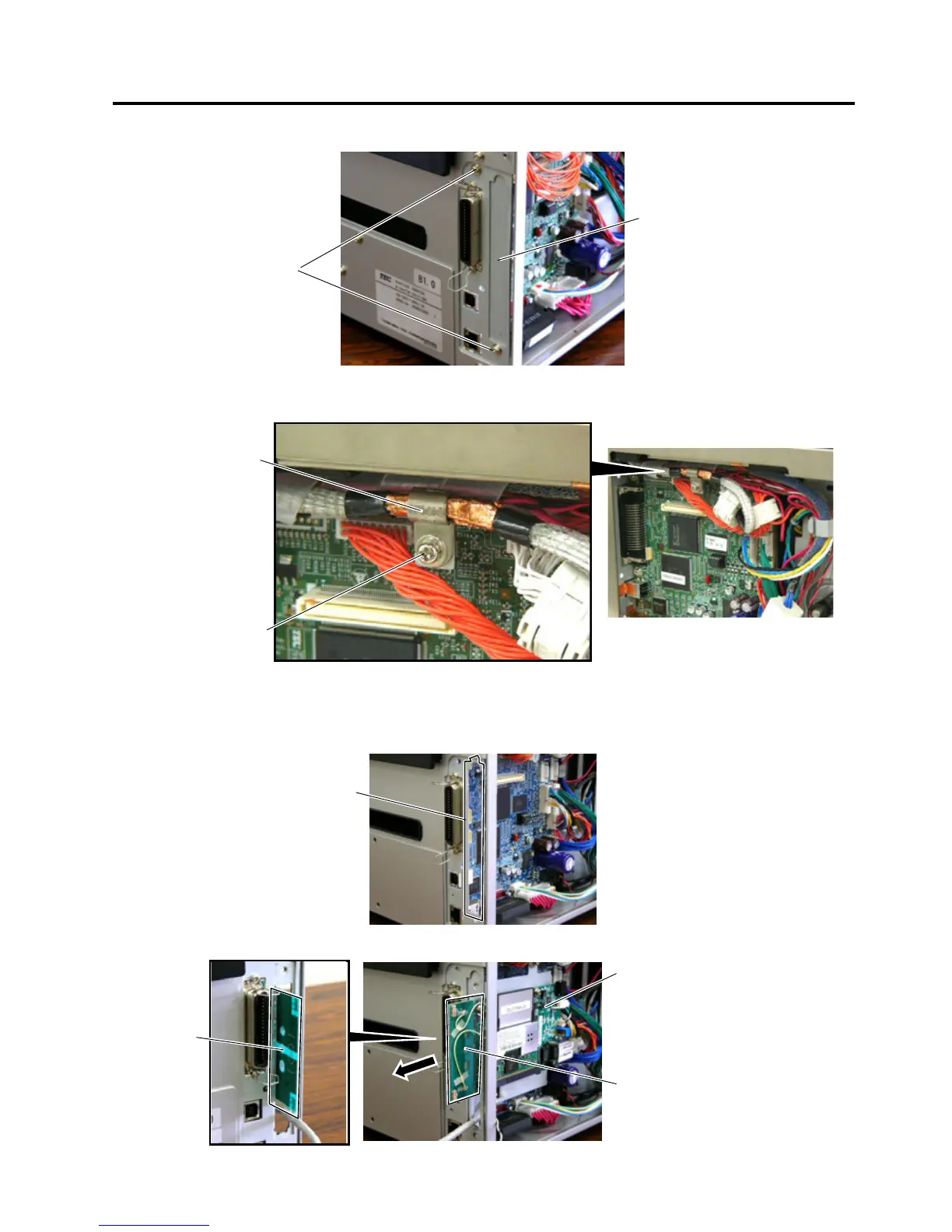
3. Remove the two SMW-3x6 screws to detach the Blind Plate.
4. Remove the SMW-3x8 screw to detach the Cable Clamp.
5. Put the Antenna of the Wireless LAN Board out of the opening in the printer back.
Care must be taken not to hit the Antenna against the printer frame, as damaged antenna may affect the
performance.
SMW-3x6
Blind Plate
Cable Clamp
SMW-3x8 Scre
w
Opening
Wireless LAN Board
Antenna
A
ntenna

Other manuals for Toshiba B-SA4T Series

Questions and Answers:

Question and Answer IconNeed help?

Do you have a question about the Toshiba B-SA4T Series and is the answer not in the manual?

Toshiba B-SA4T Series Specifications

General IconGeneral
Print TechnologyThermal Transfer / Direct Thermal
Print SpeedUp to 152.4 mm/sec (6 ips)
Max Print Width104 mm (4.09")
Resolution300 dpi
ConnectivityUSB 2.0
Optional InterfacesWireless LAN
BarcodesUPC/EAN/JAN, Code 39, Code 93, Code 128, EAN 128, NW7, Industrial 2 of 5, Postnet, RM4SCC, KIX-Code
2D CodesData Matrix, PDF417, QR Code, Maxi Code, Micro PDF417, Aztec Code
Media Thickness0.06 – 0.19 mm
Media Roll DiameterMax. 127 mm
Ribbon LengthUp to 300 m
Weight15 kg

Related product manuals