EasyManuals Logo

Toshiba B-SA4T Series User Manual

Toshiba B-SA4T Series
58 pages
To Next Page IconTo Next Page
To Previous Page IconTo Previous Page
Page #23 background imageLoading...
Page #23 background image
INSTALLATION PROCEDURE FOR OPTIONAL EQUIPMENT EO15-33001A
(Revision Date: Jan. 19, 2006)
3. Wireless LAN Module: B-SA704-WLAN-QM
3- 4
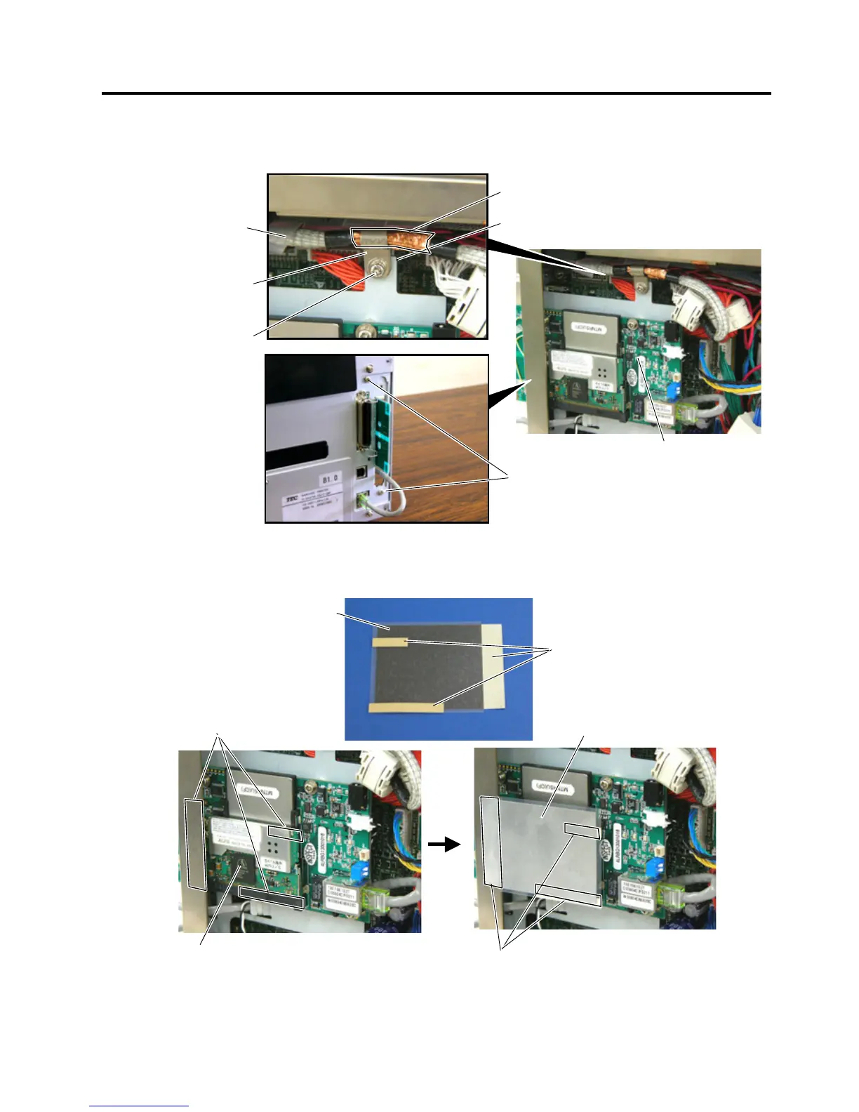
6. As the following picture shows, secure the Wireless LAN Board to the printer back with two of the
enclosed SMW-3x6 screws. Also, secure the Wireless LAN Board to the PCB Support Plate with the
SMW-3x8 screw together with the Cable Clamp removed in Step 4.
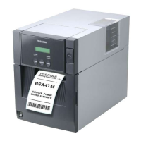
7. Only when this option is installed in the B-SA4TP printer, remove the three backing papers from the
shield sheet and attach the shield sheet so that it covers the wireless LAN module.
Wireless LAN Board
Cable Clamp
SMW-3x8 Scre
w
PCB Support Plate
SMW-3x6 Screw
Print Head Cable
Copper foil
Wireless LAN Module
Shield Sheet
Glue
Shield Sheet
Glue
Backing Paper

Other manuals for Toshiba B-SA4T Series

Questions and Answers:

Question and Answer IconNeed help?

Do you have a question about the Toshiba B-SA4T Series and is the answer not in the manual?

Toshiba B-SA4T Series Specifications

General IconGeneral
Print TechnologyThermal Transfer / Direct Thermal
Print SpeedUp to 152.4 mm/sec (6 ips)
Max Print Width104 mm (4.09")
Resolution300 dpi
ConnectivityUSB 2.0
Optional InterfacesWireless LAN
BarcodesUPC/EAN/JAN, Code 39, Code 93, Code 128, EAN 128, NW7, Industrial 2 of 5, Postnet, RM4SCC, KIX-Code
2D CodesData Matrix, PDF417, QR Code, Maxi Code, Micro PDF417, Aztec Code
Media Thickness0.06 – 0.19 mm
Media Roll DiameterMax. 127 mm
Ribbon LengthUp to 300 m
Weight15 kg

Related product manuals