EasyManuals Logo

Toshiba B-SA4T Option Installation Manual

Toshiba B-SA4T
58 pages
To Next Page IconTo Next Page
To Previous Page IconTo Previous Page
Page #27 background imageLoading...
Page #27 background image
INSTALLATION PROCEDURE FOR OPTIONAL EQUIPMENT EO15-33001A
4. Serial Interface Board: B-SA704-RS-QM-R
4- 2
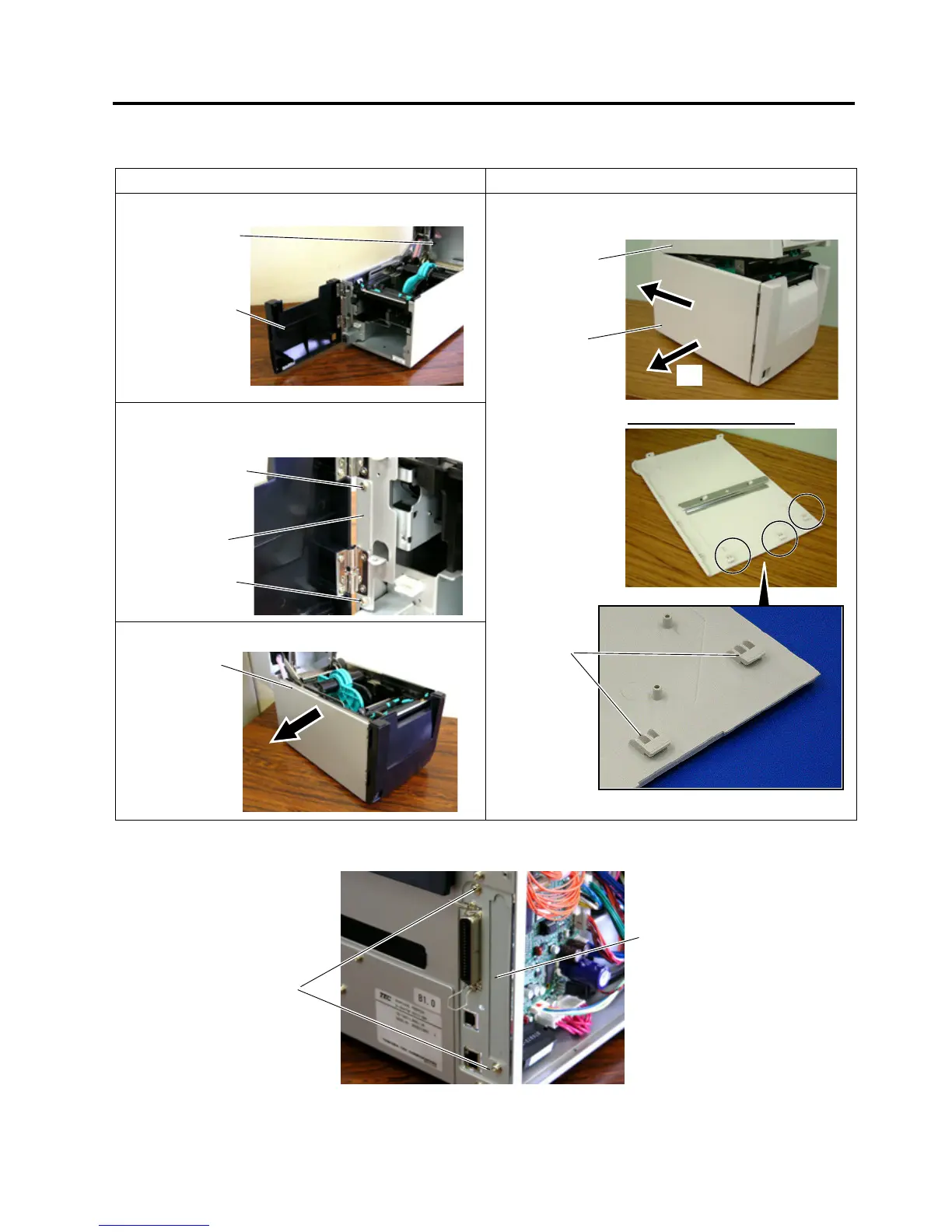
2. Remove the Side Panel in the following order. Please note the procedure is different between the B-
SA4TM series and the B-SA4TP series.
B-SA4TM B-SA4TP
(1).Open the Top Cover and Front Cover.
(2). Remove the two SMW-3x6 screws which secure
the Side Panel.
(3). Close the Front Cover and remove the Side Panel.
Open the Top Cover. Slide the Side Panel backward,
and then remove it in the direction of arrow A.
3. Remove the two screws to detach the Blind Plate.
Front Cove
r
Top Cove
r
SMW-36 Scre
w
Side Panel
SMW-36 Scre
w
Side Panel
SMW-3x6
Blind Plate
Top Cove
r
Side Panel
Reverse side of Side Panel
A
Hoo
k

Other manuals for Toshiba B-SA4T

Questions and Answers:

Question and Answer IconNeed help?

Do you have a question about the Toshiba B-SA4T and is the answer not in the manual?

Toshiba B-SA4T Specifications

General IconGeneral
Print MethodThermal transfer and direct thermal
Resolution203 dpi
Print Width104 mm
InterfacesSerial, Parallel, USB
Optional InterfacesEthernet, Wireless
BarcodesCode 39, Code 128
2D CodesPDF417, Data Matrix, QR Code, MaxiCode
Operating Temperature5°C to 40°C (41°F to 104°F)
Storage Temperature-20 - 60 °C (-4 - 140 °F)
Humidity20% to 85% (non-condensing)
InterfaceUSB, Serial (RS-232), Parallel, Ethernet, Wireless

Related product manuals