EasyManuals Logo

Toshiba B-SA4T Option Installation Manual

Toshiba B-SA4T
58 pages
To Next Page IconTo Next Page
To Previous Page IconTo Previous Page
Page #38 background imageLoading...
Page #38 background image
INSTALLATION PROCEDURE FOR OPTIONAL EQUIPMENT EO15-33001A
(Revision Date: Jan. 19, 2006)
7. Expansion I/O Board: B-SA704-IO-QM-R
7- 1
7. Expansion I/O Board: B-SA704-IO-QM-R
B-SA704-IO-QM-R is an optional expansion I/O board for the B-SA4TM/SA4TP Series. The pictures used
in this section are those of the B-SA4TP, and the installation procedures are common with the B-SA4TM
unless otherwise noted.
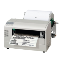
Packing List
The following parts are supplied with the kit. Make sure you have all items shown below.
Expansion I/O Board (1 pc.) See Note.
Blind Plate (1 pc.)
SMW-3x6 Screw (3 pcs.)
Installation Manual (1 copy)
Note: Make sure that the Interface Cable is connected to CN1 on the
Expansion PC Board.
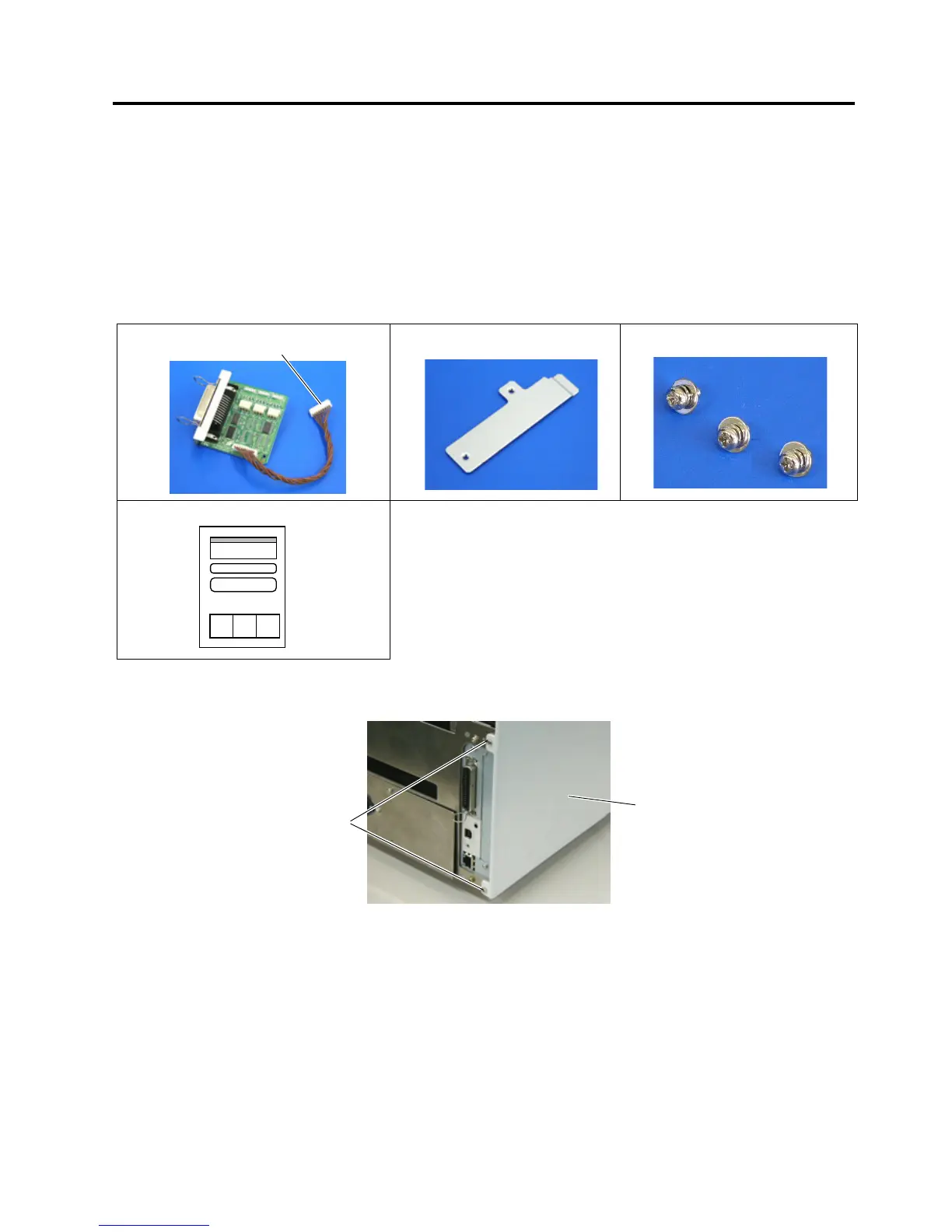
1. Remove the two SMW-3x6 screws from the back of the printer.
Interface Cable
SMW-3x6 Scre
w
Side Panel

Other manuals for Toshiba B-SA4T

Questions and Answers:

Question and Answer IconNeed help?

Do you have a question about the Toshiba B-SA4T and is the answer not in the manual?

Toshiba B-SA4T Specifications

General IconGeneral
Print MethodThermal transfer and direct thermal
Resolution203 dpi
Print Width104 mm
InterfacesSerial, Parallel, USB
Optional InterfacesEthernet, Wireless
BarcodesCode 39, Code 128
2D CodesPDF417, Data Matrix, QR Code, MaxiCode
Operating Temperature5°C to 40°C (41°F to 104°F)
Storage Temperature-20 - 60 °C (-4 - 140 °F)
Humidity20% to 85% (non-condensing)
InterfaceUSB, Serial (RS-232), Parallel, Ethernet, Wireless

Related product manuals