INSTALLATION PROCEDURE FOR OPTIONAL EQUIPMENT EO15-33001A
4. Serial Interface Board: B-SA704-RS-QM-R
4- 4
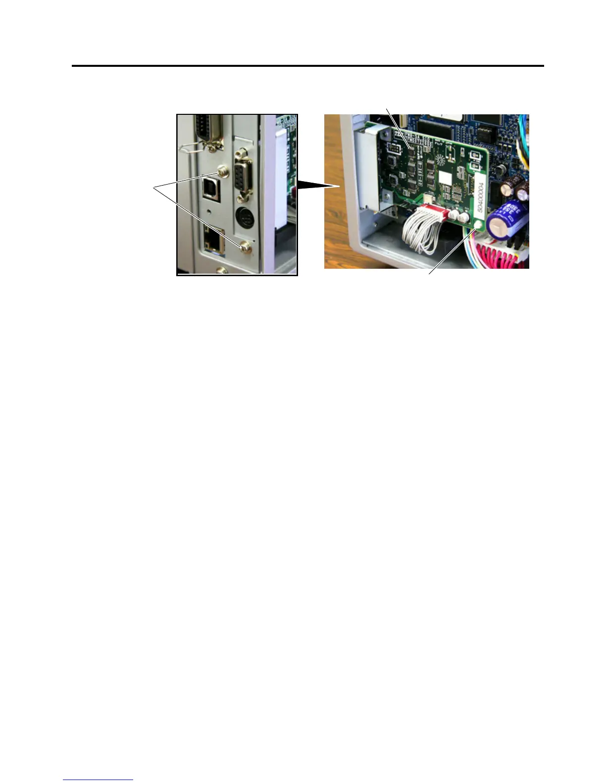
7. Secure the SIO PC Board to the printer back with the two SMW-3x6 screws. Fit the Locking Support into
the SIO PC Board.
8. Re-attach the Side Panel.
9. For an operation check, settings, etc., refer to the.
SIO PC Board
Locking Support
SMW-3x6
 Loading...