INSTALLATION PROCEDURE FOR OPTIONAL EQUIPMENT EO15-33001A
(Revision Date: Jan. 19, 2006)
7. Expansion I/O Board: B-SA704-IO-QM-R
7- 3
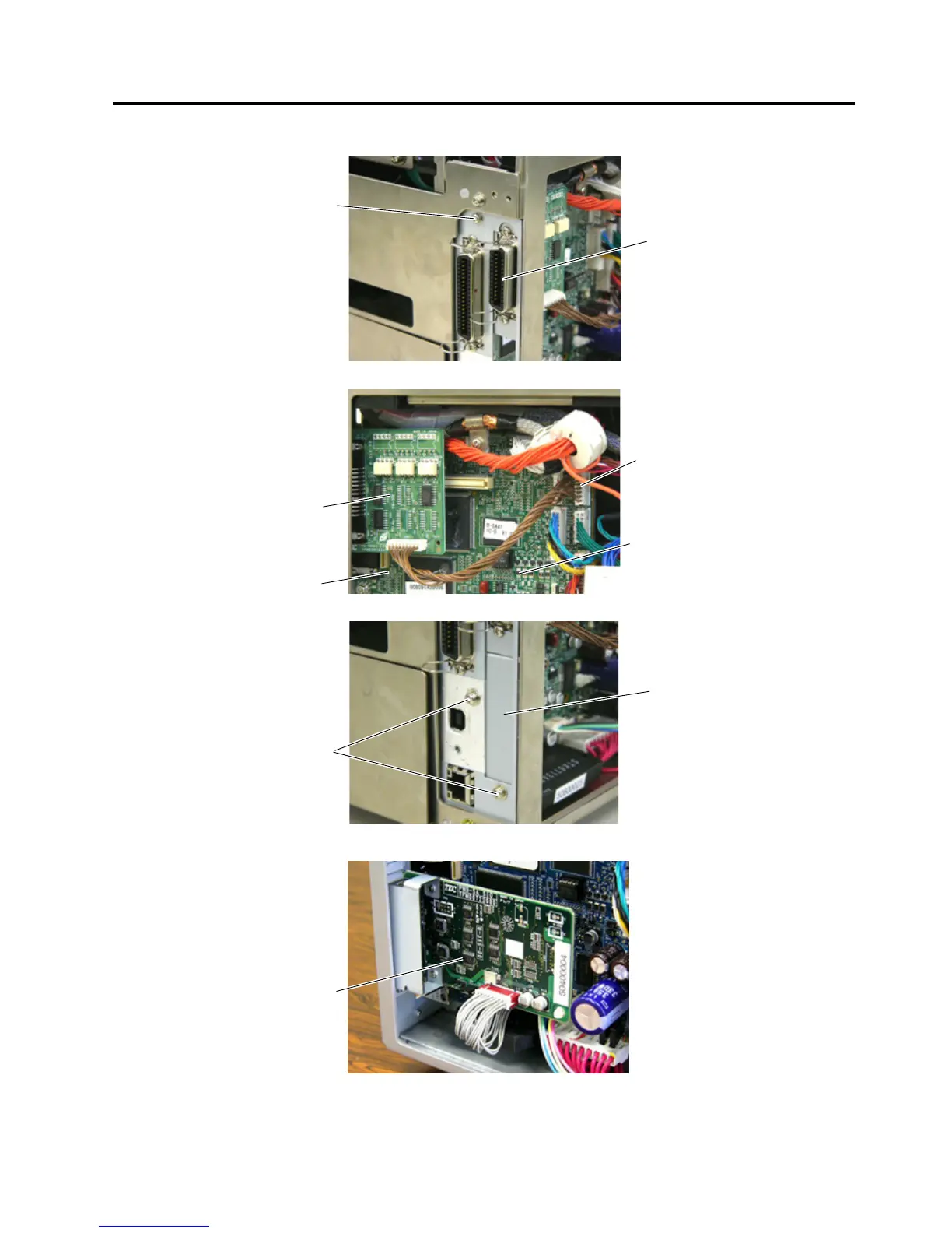
4. Attach the Expansion I/O Board to the printer back with one of the supplied SMW-3x6 screws.
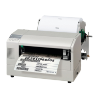
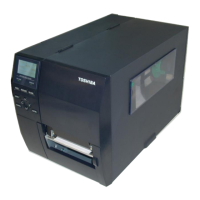
5. Connect the Interface Cable to CN4 on the MAIN PC Board.
6. Attach the supplied Blind Plate to the printer back with the supplied two SMW-3x6 screws.
NOTE: The Blind Plate is not required to be attached when the optional Serial Interface Board is also
installed.
8. Attach the Side Panel, removed in Step 2, back to the printer.
SMW-3x6 Scre
 Loading...