3.MAIN UNIT REPLACEMENT
EO18-33017
2.5 Replacing the Print Head
2- 8
2.5 Replacing the Print Head
NOTE: The following procedure can be done without removing the Left Side Cover.
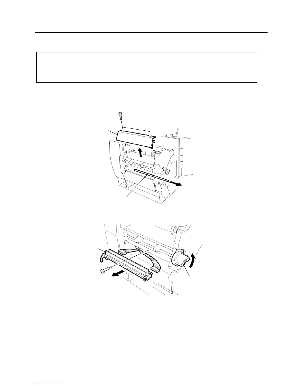
1. Remove the two B-4x6 screws to detach the Head Cover Plate.
2. Pull the Front Shaft to the right side to remove it.
3. Turn the Head Lever counterclockwise to raise the Print Head.
4. Remove the Head Fixing Screw and pull out the Print Head.
5. Disconnect the two cables and remove the Print Head.
NOTE: DO NOT separate the Print Head from the bracket.
6. Replace the Print Head with a new one, and reassemble in the reverse order of removal.
7. Refer to the System Mode Manual to clear the Maintenance Counter and perform a test print.
CAUTION!
1. DO NOT touch the thermal element when handling the Print Head.
2. DO NOT touch the connector pins to avoid damage to the Print Head by static electricity.
3. DO NOT remove the two screws painted in red on the side of the Print Block.
Head Lever
Head Fixing Scre

 Loading...