12
-EN
Central Control Device (Touch Screen Controller) Installation Manual
Termination resistance setting
•RS-485 termination resistance setting ...................Set at both ends of the RS-485 communication line. Set one end at the main
unit and the other end at the interface. The termination resistance of the main
unit is already set as a factory default. Refer to the interface installation
manual to set the termination resistance of the interface.
• TU2C-LINK / TCC-LINK
termination resistance setting ............................ <For TCC-LINK>
Leave just 1 line of the termination resistance in the interface board of the
outdoor unit (centre unit) ON, and turn all the others OFF. (Refer to the
wiring diagram attached to the outdoor unit for the position of SW.)
<For TU2C-LINK>
For the central control wiring (Uh line), set the termination resistance that is
farthest away on the wiring between this central controller and the other unit
(VRF, light commercial, air to air heat exchanger, general purpose control
interface, air to water heat pump) to ON.
Refer to the manual of each model for the termination resistance setting method.
Shield grounding process
•RS-485 cable wire shielded wire ......................... Connect to the FG terminal block.
• TU2C-LINK communication line shielded wire ......When using the system controller with one unit, open the shielded wire of the
TU2C-LINK communication line and perform insulation processing.
When using the system controller with multiple units, connect the shield of
the TU2C-LINK communication line to the closed end and open the shield at
the final end of the system controller to perform insulation processing.
Perform TU2C-LINK communication line shield grounding on the air
conditioner side.
• Be sure to install a circuit breaker or all-pole isolating switch (with a contact breaking distance of at least 3 mm) on the
primary side of the power supply.
• Fasten the screws to the terminal block with torque of 0.5 N•m.
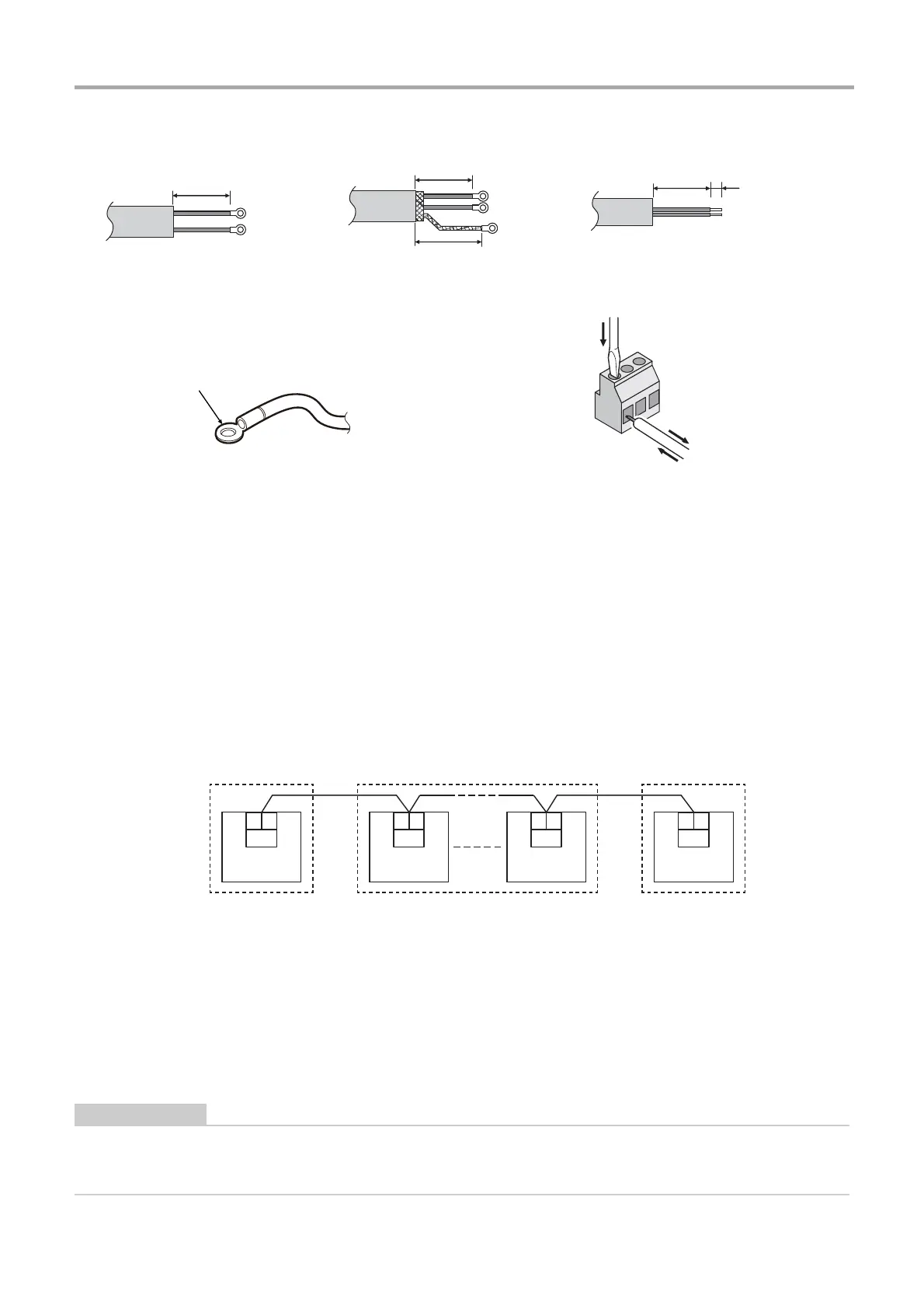
TU2C-LINK communication line stripping
length
RS-485 cable wire stripping length Digital I/O cable stripping length
Attach a round crimp terminal to each wire of the power line and
signal line.
Loosen the screws with a screwdriver, insert the digital I/O cable,
and tighten the screws securely.
U3 U4
LINK (Uh)
U3 U4
LINK (Uh)
U3 U4
LINK (Uh)
U3 U4
LINK (Uh)
Termination resistance
ON
Termination resistance
OFF
Termination resistance
ON

 Loading...