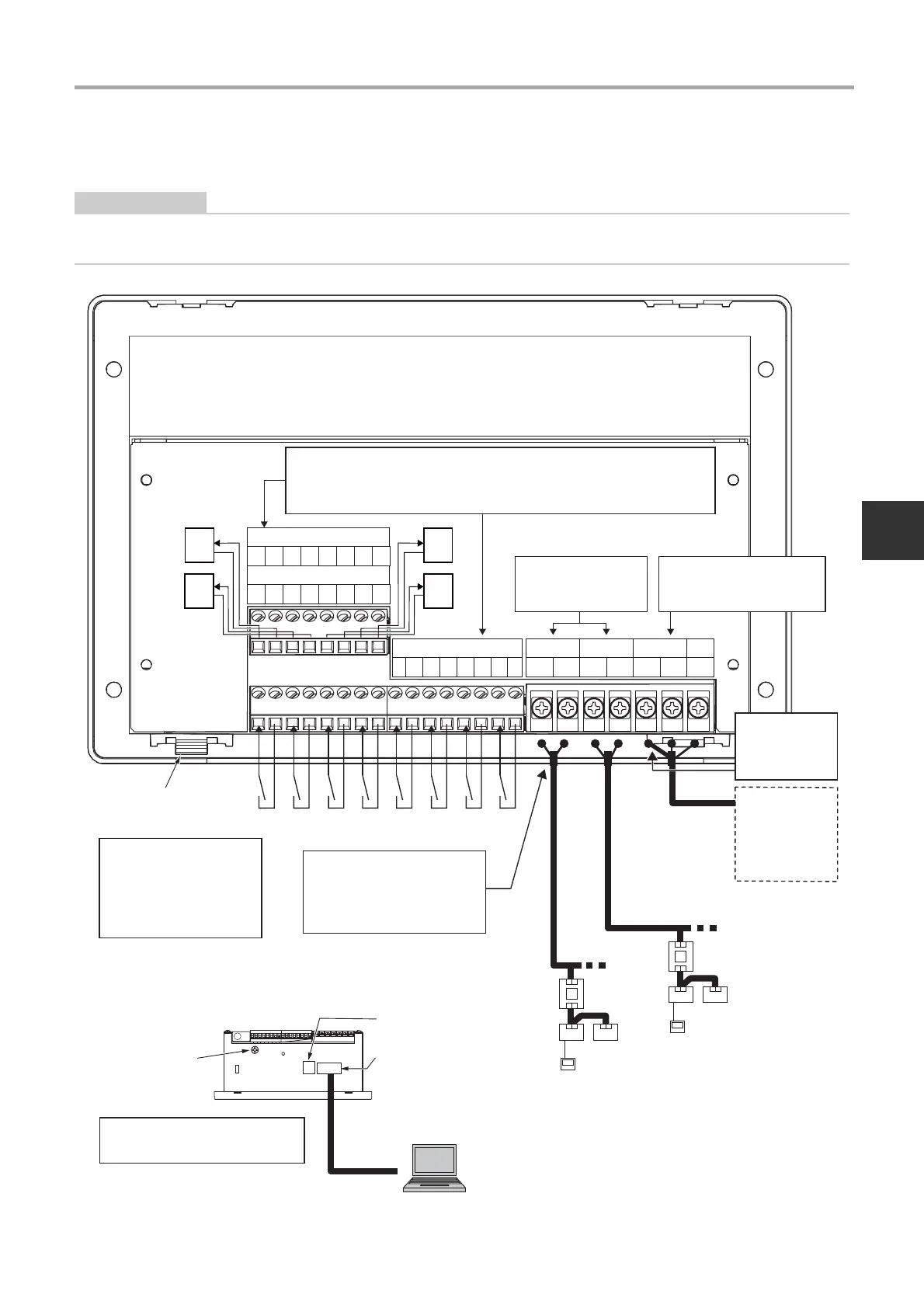
3-3. Power, Signal, and Earth Line Connections
Attach the AC adapter and
tighten securely until the screw
type fastener is fully fixed.Be
sure to connect the main unit and
the AC adapter before supplying
power to the AC adapter.
Outdoor unit
Indoor unit
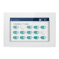
Remote controller
LINK 1
Outdoor unit
Indoor unit
Remote controller
LINK 2
RS-485 signal line
LINK1 and LINK2
terminals do not have
polarity
The RS-485 cable has polarity
(A, B). It will not work correctly if
it is connected with incorrect
polarity.
Connect the
shielded wire of the
RS-485 signal line
to the FG terminal
block.
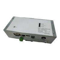
Connection with
power meter
interface/digital
I/O interface
(sold separately)
Power connector
(DC 12 V)
Connect the shield of the TU2C-
LINK communication line to the
earth on the air conditioner side.
Leave the shield open (and
insulate it). Do not connect it to the
terminal block.
LAN cable
Functional earth
Connect the functional ground terminal
to the ground near the system
controller.
For DI1 to DI8, DO1 to DO4, and each COM, use a flat head precision screwdriver
to loosen the screws and open the insertion opening. After inserting the wiring,
securely tighten the screws with a precision screwdriver so that the wiring cannot
come out. After tightening, check that the wiring cannot come out.
USB port x2
LAN port
Client

 Loading...