14
-EN
Central Control Device (Touch Screen Controller) Installation Manual
When the connected outdoor unit is Super Multi u series (U series)
Follow the wiring specifications in the table below even when there is a mix of U series and non-U series in the connected indoor
units or remote controllers.
Wiring specifications
When wiring the control wiring between indoor and outdoor units (Uv line)/control wiring between outdoor units (Uc line) and
the central control wiring (Uh line), use the same wire type and diameter for each line.
Using a mixture of different wire types and diameters may cause a communication error.
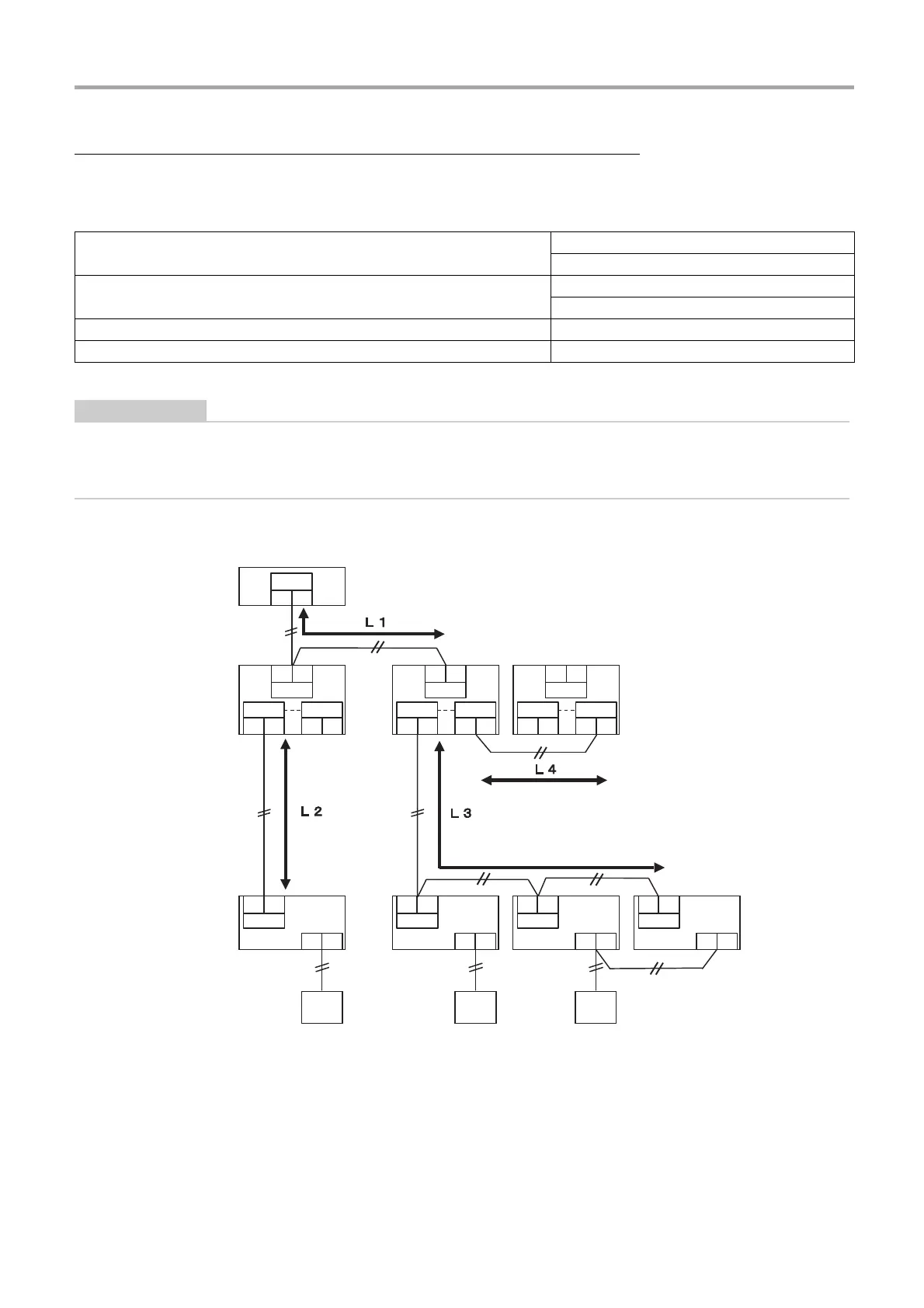
System diagram
* The wiring specifications in the system diagram above are the same even when the indoor unit or remote controller are other
than the U series.
Item
Communication line
Central control wiring (Uh line)
Wire diameter
1.0 to 1.5 mm
2
(up to 1000 m)
2.0 mm
2
(up to 2000 m)
Wire type 2-core, non-polar
Wire types that can be used Shielded wire
U3 U4
LINK (Uh)
U6
U4
U1
U2
Uv
AB
U6
U4
U1
U2
Uv
AB
U6
U4
U1
U2
Uv
AB
U6
U4
U1
U2
Uv
AB
U2
Uv
U5 U6
Uc
U3 U4
Uh
U1 U2
Uv
U5 U6
Uc
U3 U4
Uh
U1 U2
Uv
U5 U6
Uc
U3 U4
Uh
U1
System
Controller
<U series>
Outdoor unit
(Super Multi
u series)
<U series>
Indoor unit *
<U series>
Remote
controller *
[Central control wiring (Uh line)]
L1 = Up to 2000 m
[Control wiring between indoor and outdoor units (Uv
line)/Control wiring between outdoor units (Uc line)]
L2 = Up to 1000 m
(L3+L4) = Up to 1000 m

 Loading...