DISASSEMBLY INSTRUCTIONS
B3-4
Printing Surface
Reinforcement Plate
53 ± 1mm
Fold
(1)
Printing Surface
10 ± 1mm
Fold
(3)
Printing Surface
52 ± 1mm
Fold
(4)
Printing Surface
Printing Surface
10 ± 1mm
Fold
(2)
Reinforcement Plate
Reinforcement Plate
Printing Surface
Reinforcement Plate
55 ± 1mm
Fold
(1)
Printing Surface
10 ± 1mm
Fold
(3)
Printing Surface
60 ± 1mm
Fold
(4)
Printing Surface
Printing Surface
10 ± 1mm
Fold
(2)
Reinforcement Plate
Reinforcement Plate
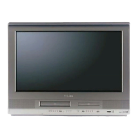
Fig. 3-7-D
Main Chassis Ass'y (Bottom Side)
Check Hook
Check Hook
Check Hook
Check Hook
• Loosen the wire in the direction of the arrow.
Double Sided Tape
Printing Surface
10mm
Fold
Fold back at the border line
of the reinforcement plate.
Fold it by 90˚
50 ± 1mm
73 ± 1mm
117 ± 1mm
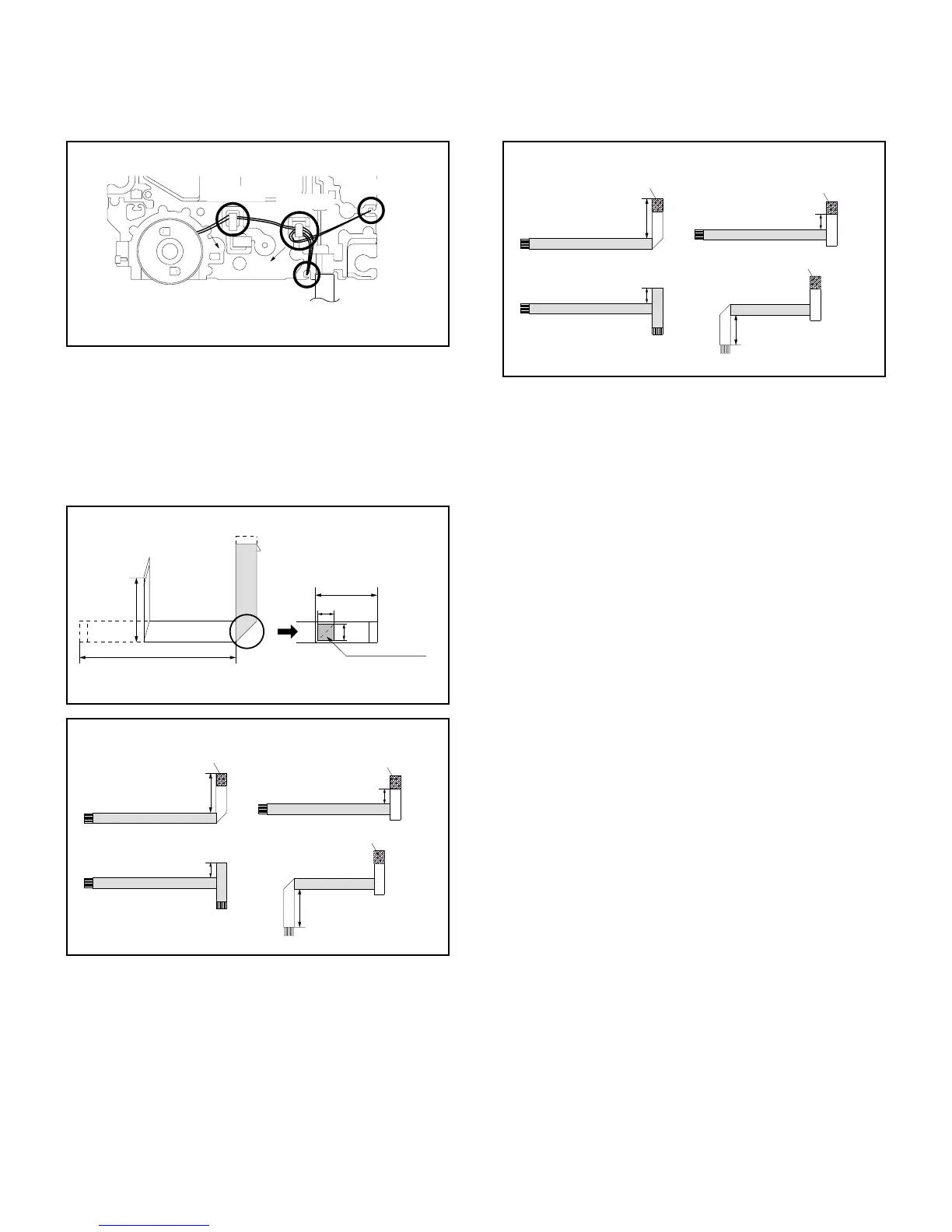
• Proceed the steps (1) through (4).
[ 24 pin FFC ]
[ 5 pin FFC ]
When installing the FFC, fold it correctly and install it as
shown from Fig. 3-8-A to Fig. 3-8-C.
3-8: FFC WIRE HANDLING
1.
Do not make the folding lines except the specified
positions for the FFC.
1.
NOTE
• Proceed the steps (1) through (4).
[ 6 pin FFC ]
Fig. 3-8-A
Fig. 3-8-B
Fig. 3-8-C
 Loading...