20 P9 ASD Quick Start Guide
FLC — FLC is the common leg of a single-pole double-throw form C relay. The FL relay is the Fault
Relay by default, but may be programmed to any of the selections listed in the P9 ASD Installation and
Operation Manual. For further information on this terminal, see F132 and Figure 8 on pg 20.
Note: The FLA, FLB, and FLC contacts are rated at 2A/120 VAC and 2A/30 VDC.
Figure 8. FLA, FLB, and FLC Switching Contacts Shown in the Normal Operating Condition.
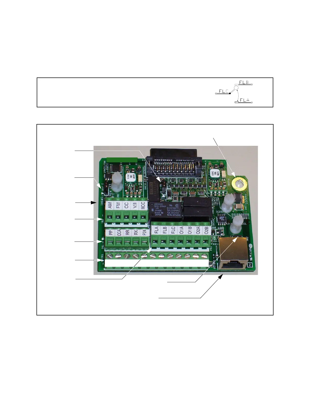
Figure 9. Terminal Board. Sink Source
See the section titled Terminal Descriptions on pg. 18 for terminal descriptions.
See the section titled Cable/Terminal/Torque Specifications on pg. 90 for information on the proper
cable/terminal sizes and torque specifications when making Terminal Board connections.
C
Note: The relay is shown in the normal operating condition. During
a faulted condition, the relay connection is FLC-to-FLA.
J101
TB1
TB2
TB3
J100
SW200
TB4
SW301
RES
CC
F
R
S1
S2
S3
S4
CC
ST
FP
+SU
Ensure that the ground screw is securely in
place to prevent arcing, intermittent
operation, or system failure.
1 to 2 = Sink (
*
)
2 to 3 = Source
1 to 2 = Sys. Supplied (
*
)
2 to 3 = Ext. Supplied
(24V)
V/I Switch (I
*
)
See Typical Connection Diagram on pg. 22 for more information on the Terminal Board.
Half / Full Duplex (
*
) Switch
CAUTION
S4
RS485 4-Wire Communication
*
= Default Setting
W301
Phone: 800.894.0412 - Fax: 888.723.4773 - Web: www .ctiautomation.net - Email: info@ctiautomation.net
 Loading...