Do you have a question about the Toshiba Satellite P205D and is the answer not in the manual?
Hazard indicating death or serious bodily injury if instructions not followed.
Hazard indicating bodily injury if instructions not followed.
Hazard indicating property damage if instructions not followed.
General information relevant to safe maintenance service.
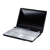
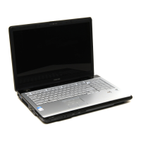
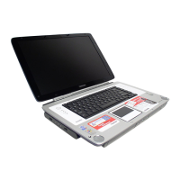
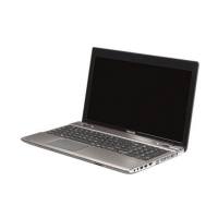
Lists the key features and benefits of the computer system.
Details the major components that constitute the system unit.
Specifications and characteristics of the 2.5-inch HDD.
Specifications for DVD Super Multi and HD DVD-ROM drives.
Performance and characteristics of the AC adapter power supply.
Lists types and specifications of main and RTC batteries.
Explains how to determine if an FRU is causing a computer malfunction.
Guide for determining troubleshooting procedures when the problem is unspecified.
Procedures to diagnose and resolve power supply issues.
Steps to determine if the computer's display is functioning properly.
Procedures to diagnose and resolve keyboard issues.
Steps to determine if external USB devices are functioning properly.
Procedures to troubleshoot TV-out port functionality.
Steps to determine if the built-in TouchPad is functioning properly.
Procedures to determine if the built-in speakers are functioning properly.
Steps to determine if the internal optical drive is functioning properly.
Procedures to determine if the computer's modem is functioning properly.
Steps to determine if the Express card player is functioning properly.
Procedures to determine if the computer's IEEE 1394 system is functioning properly.
Steps to determine if the computer's wireless LAN system is functioning properly.
Procedures to determine if the computer's camera is functioning properly.
Steps to determine if the computer's Bluetooth is functioning properly.
Steps to determine if the 4 IN 1 Card player is functioning properly.
Procedures to determine if the computer's HDD is functioning properly.
Procedures to determine if the computer's CRT port is functioning properly.
Steps to determine if the computer's HDMI port is functioning properly.
Procedures to determine if the computer's SPDIF is functioning properly.
Steps to determine if the computer's MIC is functioning properly.
Procedures to determine if the computer's Finger printer is functioning properly.
Explains how to use the Test & Diagnostic program for hardware modules.
Step-by-step guide to start and run the diagnostic program.
Shows unit configuration details including CPU, RAM, ODD, etc.
Aurally confirms speaker functions by generating beep sounds.
Tests fan operation by listening for rotating sound and wind.
Measures battery type, manufacturer, charge capacity, and function.
Includes sequential seek, funnel code, and write/read/compare subtests for FDD.
Confirms ODD functions through random read and eject door tests.
Checks all keys, requiring selection of keyboard matrix code.
Allows selection of mouse speed, acceleration, and button assignments.
Checks video display quality in Text and VGA modes.
Tests lid switch function by opening and closing the LCD cover.
Checks LAN full-duplex environment and speeds (1000, 100, 10 Mbps).
Compares DOS and CMOS values for Real Time Clock and calendar functions.
Checks if the computer's EEPROM 1394GUID code is correct.
Checks and rewrites EEPROM EQ type, requiring speaker type selection.
Checks if the computer's EEPROM SKUID is correct.
Sets the SKUID in EEPROM, requiring button number selection.
Enables or disables the Front Edge Logo function via program or BIOS.
Checks if the computer's Fingerprint function is OK by swiping finger.
Clears all fingerprint information from the TBX module.
Allows writing OEM string, version, serial, or product data to DMI.
Allows double checking of DMI data like manufacturer, product name, serial.
Verifies the 1st HDD status through various test methods.
Verifies the 2nd HDD status through various test methods.
Manually tests each of the five CD control buttons on the front panel.
Guide to disassembling the computer and replacing FRUs.
Instructions for removing and installing the battery pack.
Steps for removing and installing a PC Card.
Procedures for removing and inserting a memory card.
Steps for removing and installing the main and secondary HDD.
Procedures for removing and installing the expansion memory module.
Instructions for removing and installing the modem module.
Steps for removing and installing the optical drive module.
Procedures for disassembling and reassembling the optical drive.
Instructions for removing and installing the keyboard.
Procedures for removing and installing the display assembly.
Steps for removing and installing the function button board.
Instructions for removing and installing the wireless LAN unit.
Procedures for removing and installing the Bluetooth module.
Steps for removing and installing the top cover.
Instructions for removing and installing the Touch Pad.
Procedures for removing and installing the fingerprint module.
Steps for removing and installing the speakers.
Instructions for removing and installing subwoofer and USB boards.
Procedures for removing and installing the system fan.
Steps for removing and installing the CRT PCB.
Instructions for removing and installing the system board.
Procedures for removing and installing the VGA board.
Steps for removing and installing the fan, heat sink, and CPU.
Instructions for removing and installing the display mask.
Procedures for removing and installing the FL inverter board.
Steps for removing and installing the LCD module.
Instructions for removing and installing the camera and microphone.
Essential precautions for safe handling and preventing damage to the LCD module.
Visual diagrams of system board connectors and ICs (Top/Bottom views).
Detailed lists of system board connectors and integrated circuits.
Pin assignments for various system board connectors like SODIMM, HDD, USB, etc.
Comprehensive tables of keyboard scan codes (Set 1, Set 2, Fn key, etc.).
Detailed list of screws, their locations, and required torque values.
Mean Time Between Failures (MTBF) data for key computer components.