INTERFACE MANUAL
Specifications of
non-voltage
contact and
transistor
• Non-voltage contact specifications
Contact rating DC24 V, 10 mA or over
Circuit current: Approx. 7 mA
Minimum current DC 24 V, 1 mA
Contact impedance 100 Ω or less
• Transistor specifications
Withstand voltage between collector and emitter
30 V or over
Current between collector and emitter
10 mA or over
Circuit current: Approx. 7 mA
Leakage current between collector and emitter
100 µA or less
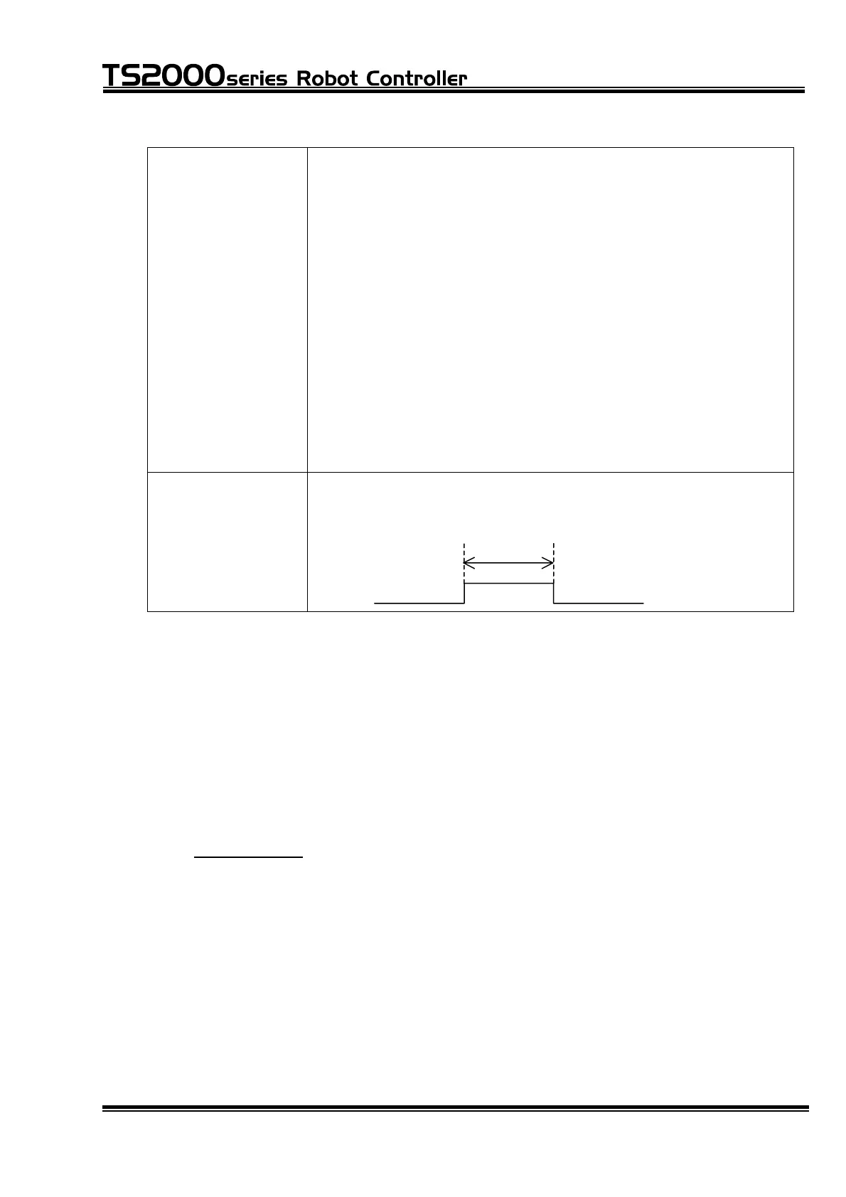
Signal timing When the pulse type input signals are used, the pulse width
should be 100 ms or over.
DI_1~DI_38
100 ms or over
* When using the system input signals as the digital input signals:
When "Default" (standard PLC) is specified by user parameter [U11] (I/O mode),
you can select whether INPUT23, 24, 33 ~ 38 are the system input signals or
digital input signals.
User parameter [U13]
[U13] Select input signal (Default I/O mode only)
{Input 23,24,33,34,35,36,37,38} (0: System 1: User)
= 1 1 0 0 0 0 0 0
Specify "1" for a desired bit underlined above, and appropriate system input
signal can serve as the digital input signal. Respective bits signify DI_23, DI_24,
STROBE, PRG_RST, STEP_RST, CYC_RST, DO_RST and RUN when viewed
from the left, which correspond to digital signals DI_23, 24, 33 ~ 38.
STE 71367
– 37 –

 Loading...


