INTERFACE MANUAL
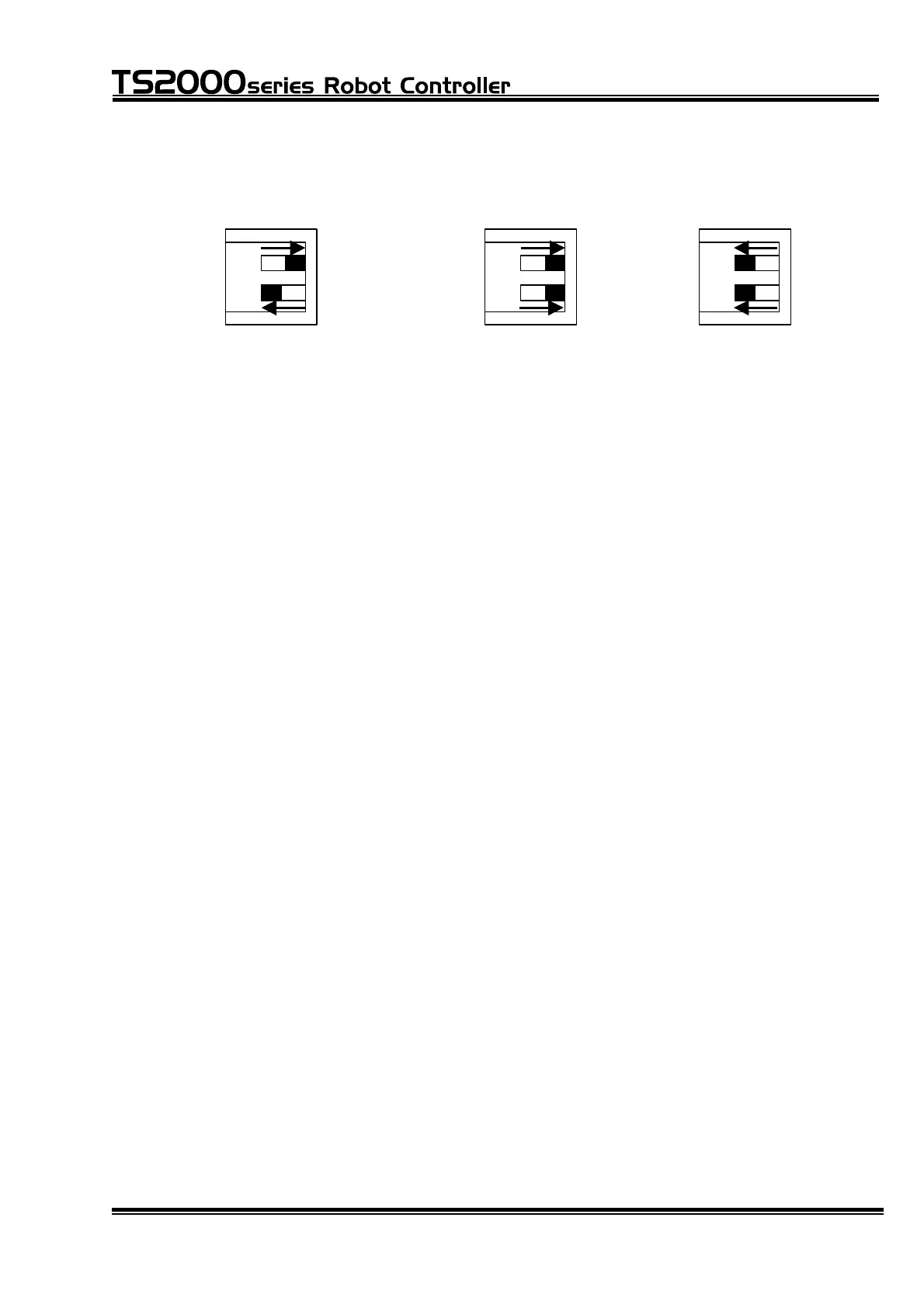
Ex.1 When adding one (1)
TR48DIOCN/TR48DIOC
Ex.2 When adding two (2)
TR48DIOCN/TR48DIOC
1 2
1
ON
0
OFF
1 2
1
ON
0
OFF
1 2
1
ON
0
OFF
The slave station setting is already described above. Specify the slave station
of TR48DIOCN/TR48DIOC to be used, according to the station number set in
USER. PAR.
For the terminator, when only one (1) TR48DIOCN/TR48DIOC module is used,
set ON the terminator setting switch equipped on the module.
When two (2) TR48DIOCN/TR48DIOC modules are used, see Fig. 7.4 for
example. As the TR48DIOCN/TR48DIOC module on the extreme right side as
viewed from the controller rear side is the terminal station in terms of cable wiring,
set ON the terminator setting switch equipped on this module alone. The
terminator of the left TR48DIOCN/TR48DIOC module should remain OFF.
When using the TR48DIOCN/TR48DIOC module, careful precautions should be
taken on the following matters.
[1] Make sure that the slave station number set in "USER.PAR" coincides with
the station number setting of the TR48DIOCN/TR48DIOC module.
[2] When the TR48DIOCN/TR48DIOC module or modules are connected, set
ON the terminator setting switch equipped on the TR48DIOCN/TR48DIOC
module which is located on the extreme right side in terms of cable wiring
when seen from the controller.
Be sure to execute Items [1] and [2] above, irrespective of the presence or
absence of external power supply. Otherwise, the system may not function
normally or go wrong.
With the above setting, make sure that both the POWER and RUN LEDs on each
TR48DIOCN/TR48DIOC module are illuminated.
STE 71367
– 96 –

 Loading...


