16
model 3000 DeviceNet Module Manual (DN311/DN311A)
Chapter 2 Names and Functions of the Parts of the DN311
2
2.2 Functions of the Parts
(1) Module status and network status LEDs (MS/NS)
These LEDs light in two colors, green and red, and blink to indicate the DN311's
module status (MS) and network status (NS).
(* 1) See 4.3.5 Operation mode control request for a description of run mode.
(* 2) Busoff: Individual DeviceNet nodes check one another for transmission line errors.
If the local node is judged to be the cause of frequent transmission line
errors, it is disconnected from the transmission line. This state is called
busoff.
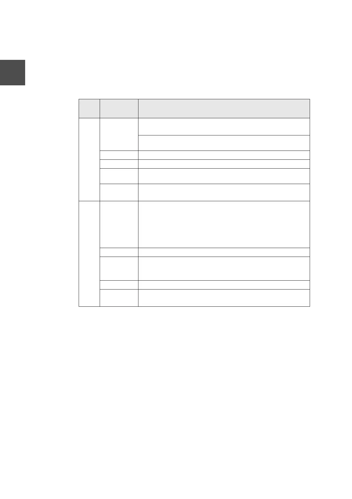
Table 2-1 LED Indications
LED
Status
indicated
Meaning (Main trouble)
MS OFF • No power is supplied to the DN311.
• Power is supplied to the DN311, but it is not in run mode (* 1).
Power is supplied if the 7-segment LED for node address/error code
indicates the local station node address.
Green ON • The DN311 is operating normally.
Blinking green • The DN311 is reading switch settings.
Blinking red • The DN311 has developed a recoverable trouble.
→ Switch (DIP switch/rotary switch) setting error, for example
Red ON • The DN311 has developed a non-recoverable trouble (down status).
• The module may have to be replaced.
NS OFF • No power is supplied to the DN311 (check MS).
• Power is supplied to the DN311, but it is not in run mode ( * 1);
(Check MS.)
• The DN311 has developed a non-recoverable trouble (down status);
(Check MS.)
• No network power is supplied to the DN311.
Green ON • The DN311 is communicating normally with slave devices.
Blinking green • No communication between the DN311 and slave devices is estab-
lished.
• No slave devices are registered in the DN311.
Blinking red • Communication has failed with more than one slave device.
Red ON • Communication has stopped due to DN311 busoff (* 2).
• Communication has stopped due to duplicated node address.
 Loading...