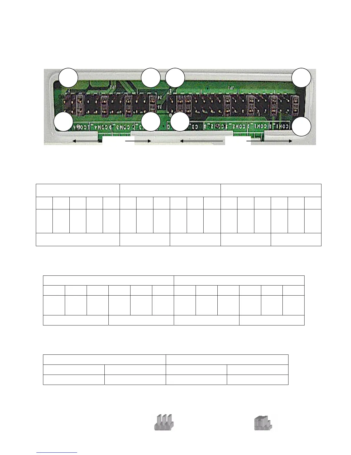
B-2 I/O Board
Tilt the terminal and remove the Jumper Cover Plate (1 screw) on the bottom of the
terminal to gain access to the jumpers.
2
1
24 2 34
23
JP1
33
1
JP2
COM1/COM2/Cash Drawer DC Power Jumper Setting: JP1 (SHORT)
Cash Drawer COM2 COM1
1-2 3-4 5-6 7-8 9-10 11-12 13-14 15-16 17-18 19-20 21-22 23-24 25-26 27-28 29-30 31-32 33-34
NC +24V
◎
+24V
◎
+12V
+12V
+12V +5V RI
◎
+12V +5V
DCD
◎
+12V +5V RI
◎
+12V +5V
DCD
◎
PIN9 PIN1 PIN9 PIN1
◎Factory Default Setting
COM3/COM4 DC Power Jumper Setting: JP2 (SHORT)
COM4 COM3
1-2 3-4 5-6 7-8 9-10 11-12 13-14 15-16 17-18 19-20 21-22 23-24
+12V +5V RI
◎
+12V +5V
DCD
◎
+12V +5V RI
◎
+12V +5V
DCD
◎
PIN9 PIN1 PIN9 PIN1
◎Factory Default Setting
USB DC Power Jumper Setting: JP3/JP4 (SHORT)
JP3 (SHORT) JP4 (SHORT)
1-2 3-4 1-2 3-4
+24V
◎+12V ◎+24V
+12V
◎Factory Default Setting
Note:
OPEN
SHORT
34