- 24 - tousek / E_PULL-T24-T24speed_49002410 / 06. 08. 2019
6a
S
S
A
D
D
E
FE
Important
• With the use of the 2-channel-receiver the second
channel takes over the function of the pedestrian
entry mode switch.
• For programming of receiver please see manual for
radioreceiver.
Important notes after installation
• Installation, connection, adjustments, putting into operation, and servicing may only be carried out by trained
professionals in full accordance with these installation- and operating instructions.
• The packaging materials (cardboard, plastic, EPS foam parts and lling material etc.) have to be properly disposed of
in accordance with the applying recycling and environmental protection laws. They may be hazardous to children and
therefore have to be stored out of children´s reach.
• The product is not suitable for installation in explosion-hazardous areas.
• The product may only be used in accordance with its original purpose, for which it has been exclusively designed, and
which is described in these installation and operating instructions (especially children have to be instructed). The TOUSEK
Ges.m.b.H. rejects any liability if the product is used in any way not fully conforming to its original purpose as stated
herein.
• All electrical installations have to be made in full conformity with the applying rules and laws (e.g. using a fault
current circuit breaker, proper grounding etc.).
• An all-pole disconnecting main switch with a contact opening-gap of minimum 3 mm has to be foreseen.
• The electric motor heats up during operation. Therefore the device should only be touched after it has cooled o.
• After installation the proper function of the gate facility and the safety devices has to be checked!
• The installer has to inform the user about all aspects of the automatic operation of the complete gate facility, as well as
about emergency operation. The installer further has to supply to the user all instructions relating to the safe operation
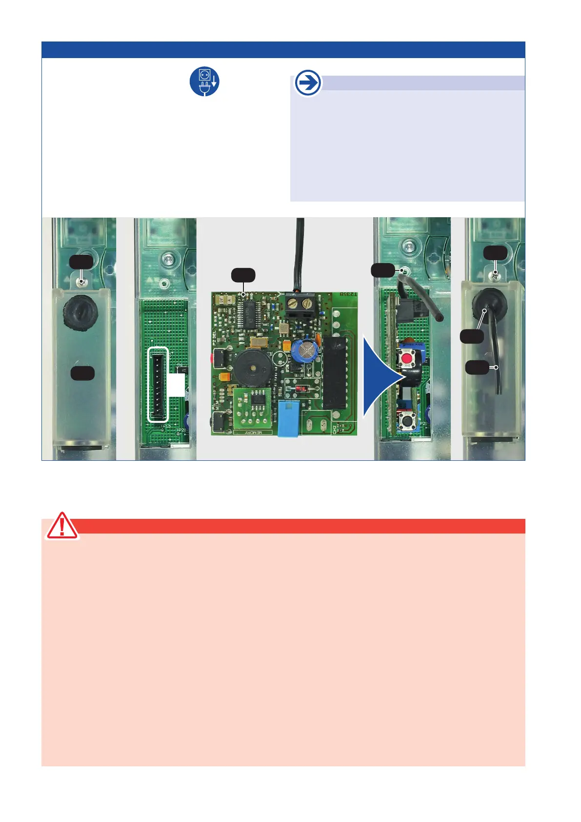
• Disconnect the power supply.
• Remove radio cover (6a) after loosening the bolt (S).
• Plug-in the receiver printed circuit board (E) RS433/868-
STN1 (1 channel) or RS433/868-STN2 (2 channels) into
the corresponding slot (FE) as shown in the picture.
• Slide the antenna cable (D) through the output connection
(A).
• Place the radio cover (6a) back and x it with bolt (S).
• To increase the range an external antenna FK433 or FK868
can be connected.
4. Connecting the receiver Sliding gate operator PULL T24, -T24speed