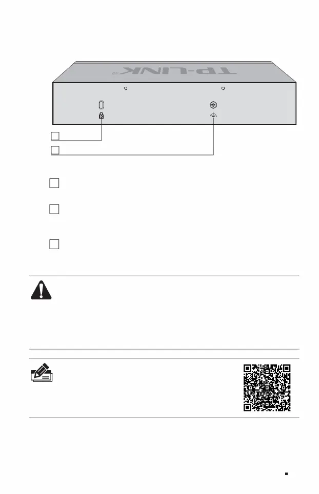
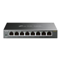
The rear panel of TL-ST2008 is shown in Figure 1-5.
2 anti-theft lock holes
2Anti -theft lock hole uses an
anti-theft lock chain, one end is inserted into the lock hole, and the other end is fixed on an immovable object to prevent the switch from being accidentally moved.
3 Lightning protection grounding posts
Full 10G Cloud Managed Switch Installation Manual
3. For lightning protection grounding
posts, please use copper core wires with yellow and green sheaths for grounding to prevent lightning strikes. For details, please refer to the "Lightning Protection
Installation Manual".
1 Power interface The DC
power interface of TL-ST2005 is connected to the 12VDC/2.5A DC power supply.
Product introduction 05
Note: ÿ
Please use the original power adapter. ÿ The
power adapter is used as a disconnecting device and the socket should be easily
accessible. ÿ Keep away from water, fire, humid or hot
environments. ÿ Please do not attempt to disassemble, repair or
modify the device. ÿ Do not replace the battery, otherwise there is a risk of explosion.
Figure 1-5 Schematic diagram of the rear panel of TL-ST2008
Note:
The product label is located on the bottom of the switch. Scan the QR code on
the right to view the meaning of product-related safety symbols.
Machine Translated by Google