Copyright © 2012 Test Products International, Inc. 9070 Vibration Analysis
PAGE 4
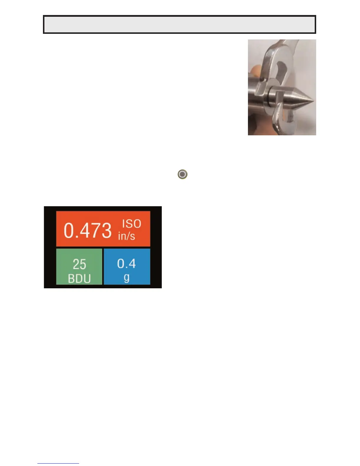
2.1 Changing the probe tip
Warning: In order to prevent possible damage,
the probe tip should only be tightened using the
machined flats on the probe tip’s mounting plate
and 8mm & 16mm wrenches, as illustrated in the
photo opposite. Do NOT hold or clamp the case of
the Vib Meter when tightening the probe tip or
magnet, as this may cause damage and will invali-
date the warranty.
2.2 Taking a reading
To take a reading, briefly press the circle button to turn the unit ON
and then, while holding the tip of the unit against the machine to be
measured, press the circle button again to take the reading.
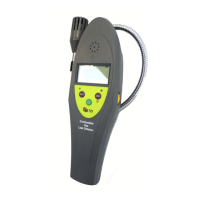
This causes the overall vibration
numbers screen to be displayed as
shown in the example screenshot on
the left.
This shows an overall view of the
machine’s vibration condition as
explained in the following sections.
2.2.1 Vibration readings
Once a vibration reading has been taken, the display will show three
values, as shown in the screenshot above.
• ISO value (velocity in mm/second or in/sec)
• Bearing Noise in BDU (Bearing Damage Units)
• Total g (acceleration)
According to ISO standards, values will display on a Green background
indicating a new machine condition, Amber background indicating unlim-
ited long term operation allowable, and Red background indicating vibra-
tion causes damage. Total g (acceleration) always displays on a Blue
background. These readings are explained in more detail below with
some examples of what they actually mean:
2 Operation