Do you have a question about the TPI DC710 and is the answer not in the manual?
Overview of the DC710 combustion analyzer, its sensors, and maintenance recommendations.
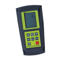
Identifies and describes the components visible on the front panel of the DC710.
Identifies and describes the components visible on the back panel of the DC710.
Details the Lithium Ion rechargeable battery and its status indicator in the TPI View App.
Step-by-step guide on powering on the DC710 and connecting it to the TPI View app.
Procedure for safely turning off the DC710 analyzer, including pump and app disconnection.
Explains the importance of combustion analysis and general guidelines for testing.
Discusses factors for accurate and consistent combustion tests, including sample location.
Instructions for turning on the DC710 and connecting to the TPI View app.
Details connecting the pump protection filter, flue probe, and temperature probes.
Guidance on drilling a 1/4 inch sample hole in the flue, including location calculations.
Procedure for inserting the flue probe and ensuring correct water trap orientation.
How combustion analysis readings are displayed on the TPI View app and parameter explanations.
Instructions for generating and sending test reports via email or Bluetooth printer.
Illustrates typical flue probe locations for gas-fired fan assist boilers and furnaces.
Illustrates typical flue probe locations for condensing boilers and furnaces.
Illustrates typical flue probe locations for atmospheric forced air furnaces.
Typical test results for Oxygen, Carbon Monoxide, Stack Temperature, and Draft for gas-fired power burners.
Typical test results for Oxygen, Carbon Monoxide, Stack Temperature, and Draft for oil-fired power burners.
Typical test results for gas-fired atmospheric/fan assist burners.
Details for the DC710 instrument, including operating range, battery, dimensions, and sensors.
Specifications for the flue temperature probe, including construction, length, and accuracy.
Specifications for gas measurements (Oxygen, CO, CO2, Ratio, Efficiency) including range, resolution, and accuracy.
Specifications for temperature measurement, including input type, range, resolution, and accuracy.
Details Bluetooth version, FCC ID, and IC for the DC710.
Recommends annual calibration and provides contact information for service.
Lists consumable parts for the instrument, including filters and sensors, with part numbers.
Details the 3-year warranty for the DC710 and instructions for warranty service.
Outlines the recommended maintenance schedule for the analyzer, including checks and frequency.
Provides steps for visually inspecting the water trap for damage or wear.
Explains how to check the mini pump protection filter and other filters for discoloration or saturation.
Procedure to check the analyzer pump's operation by covering the inlet and observing flow.
Steps to check the integrity of the flue probe, pump, and connections for leaks or faults.
Step-by-step guide for installing the A773 sulfur filter into the flue probe hose.
Guidance on when to replace the A773 sulfur filter pellets and how to dry and reuse it.
Step-by-step guide to replace the CO and O2 sensors in the DC710 analyzer.
Instructions on how to remove the rubber hoses and pull the sensor from its holder.
Guidance on orienting and installing the new sensor into the sensor holder and main board.
Connecting hoses to the new sensor, repeating for the other sensor, and reassembling the housing.
Important notes on waiting 24 hours for sensor acclimation and the need for factory calibration.
Notes on how air filters, obstructions, and air leaks impact combustion efficiency.
Discusses the impact of gas manifold pressure on combustion efficiency and the need for manufacturer specs.
Explanation of Gross vs. Net efficiency calculations and their usage regions.
Information on CO properties, common sources, and how it affects the body.
Details common symptoms of CO poisoning and risks for vulnerable individuals.
Chart detailing CO concentration levels, exposure times, and corresponding toxic symptoms.
| Brand | TPI |
|---|---|
| Model | DC710 |
| Category | Measuring Instruments |
| Language | English |