Printed in the Federal Republic of Germany TR-Electronic GmbH 2003, All Rights Reserved
02/13/2017 TR - ELA - TI - GB - 0040 - 06 Page 15 of 22
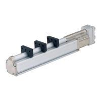
Pos. 1 Nut
Pos. 2 Clamping ring
Pos. 3 Inner O-ring
Pos. 4 Screw socket
1. Cut shield braid / shield foil back to dimension "X" + 2mm.
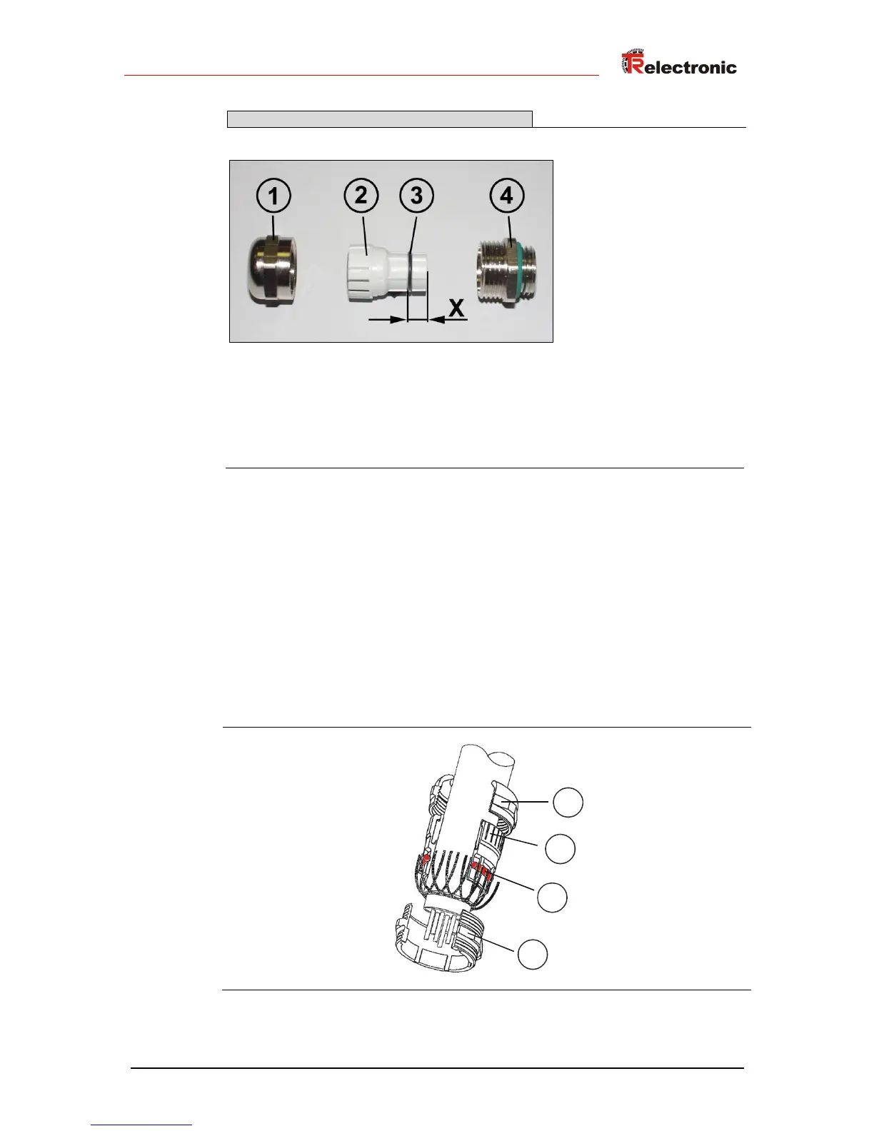
2. Slide the nut (1) and clamping ring (2) over the cable.
3. Bend the shield braining / shield foil to approx. 90°.
4. Push clamping ring (2) up to the shield braid / shield foil and wrap the
braiding back around the clamping ring (2), such that the braiding goes
around the inner O-ring (3), and is not above the cylindrical part or the torque
supports.
5. Assemble screw socket (4) on the housing.
6. Insert the clamping ring (2) in the screw socket (4) such that the torque
supports fit in the slots in the screw socket (4).
7. Screw the nut (1) to the screw socket (4).