TR-Electronic GmbH 2003, All Rights Reserved Printed in the Federal Republic of Germany
Page 16 of 22 TR - ELA - TI - GB - 0040 - 06 02/13/2017
6 Commissioning
6.1 CAN interface
The CAN field bus interface (separated via optoelectronics with CAN-BUS-Driver
PCA82C250T) in the measuring system is determined according to the international
standard ISO/DIS 11898 and covers the two lower layers of the ISO/OSI reference
module.
The transformation of measuring system information into the CAN protocol occurs by
the protocol chip SJA1000. The function of the protocol chip is monitored by a
watchdog.
The PREDEFINED MASTER/SLAVE CONNECTION SET is used for the measuring
system who only works as a slave. It will be used only the Group 2 Messages with
the exception of the Group 1 Message For Slave I/O Poll Response.
Establishing or breakdown of a connection must occur via Group 2 Only
Unconnected Explicit Request Message.
The measuring system contains an I/O Communication Port and an Explicit
Message Communication Port. The I/O communication port is used for polling the
measuring system position and must be made accessible by setting the watchdog
(after the I/O connection master/slave was set up before). Is the I/O port not
retriggered (polled) punctually the connection is interrupted and the red LED flashes.
The connection for the I/O port must be installed again.
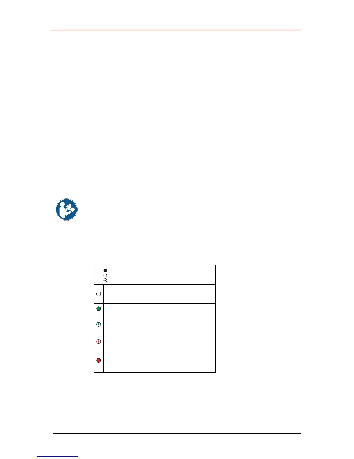
Online, with connections in the established state
- Device is allocated to a master
DUP-MAC-ID test successful
- No allocation to a master
Recoverable faults
- I/O-connections are in the time-out state
- Measuring system has not detected any magnet
- Turn off system --> turn on system
- Replace measuring system device