48,&.,167$//
&RS\ULJKW7UDFH(QJLQHHULQJ&R,QF 7HOHSKRQH 3DUW1XPEHU
WK
6WUHHW1( )D[ 2FWREHU
$UOLQJWRQ:$86$ ZZZWUDFHHQJLQHHULQJFRP
3DJH
•
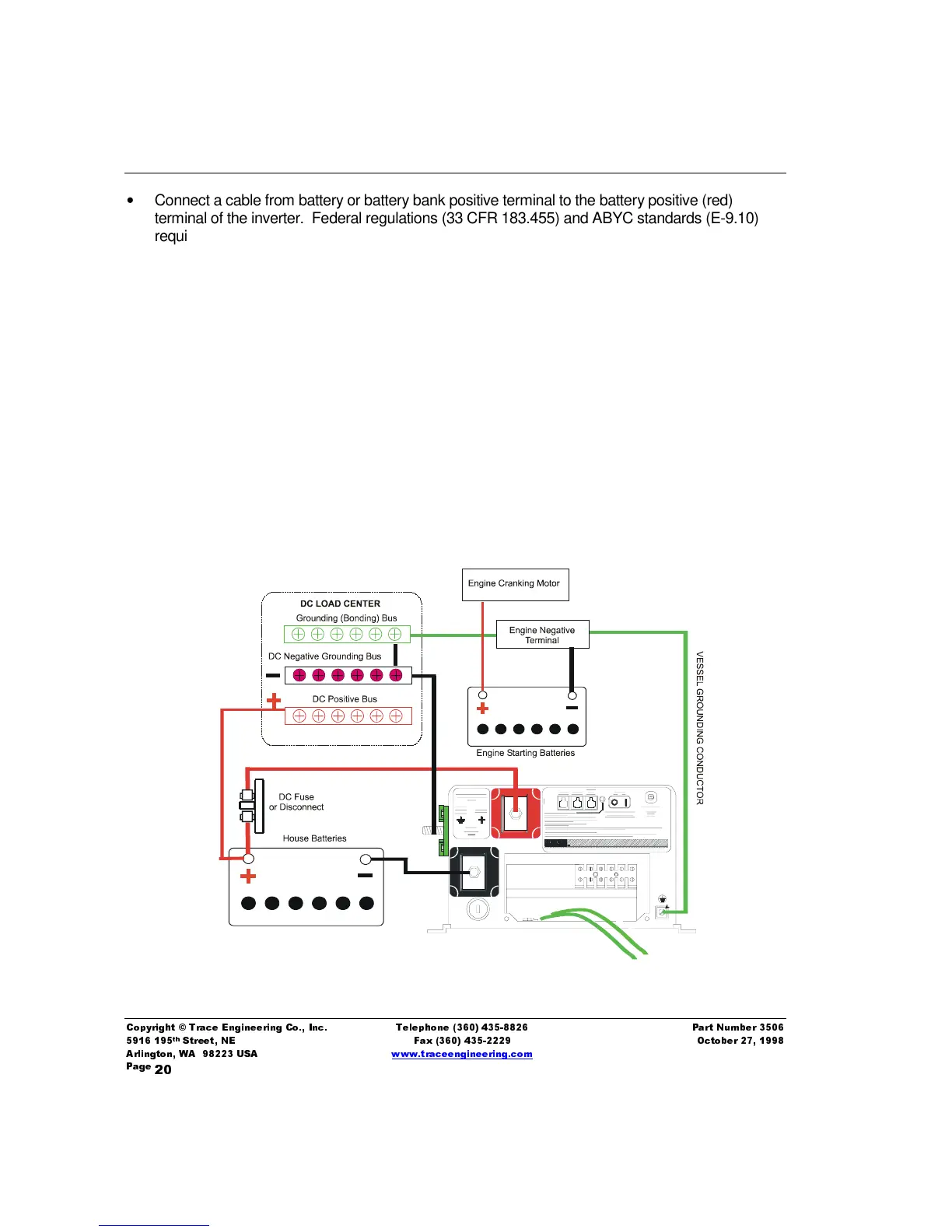
Connect a cable from battery or battery bank positive terminal to the battery positive (red)
terminal of the inverter. Federal regulations (33 CFR 183.455) and ABYC standards (E-9.10)
require an overcurrent device (fuse or circuit breaker) in this conductor. Install a DC fuse (Trace
part number TFBXXX) or circuit breaker within 72-inches of the battery terminal in this cable.
•
Connect an appropriate sized cable from the DC source negative terminal to the negative (black)
terminal on the inverter.
•
Connect a cable from the DC Negative Bus Terminal (green terminal) on the inverter to the DC
negative bus in the vessel’s DC distribution center. Torque all terminals to 12 foot-pounds.
•
Connect a conductor from the DC Grounding terminal (chassis ground) on the front of the
inverter to the DC Grounding bus (’green wire’), which is connected to the engine negative
terminal. Do not connect to the DC Load Center Negative bus.
•
Connect the DC negative conductor from all DC loads to the DC negative bus of the DC load
center or distribution center. This enables the inverter’s Fuel Gauge feature. Never connect DC
negative conductors to the DC Grounding Bus (green wire) as this bus is not intended as a
conductor, except in the event of current leakage.
Figure 3, Typical DC Wiring Diagram